background image

Page 23 of 68

Doc. P/N: 

WSP-009-002

Version: V2.3 
Issue Date:  July 2014

Installation Manual

www.wassp.com

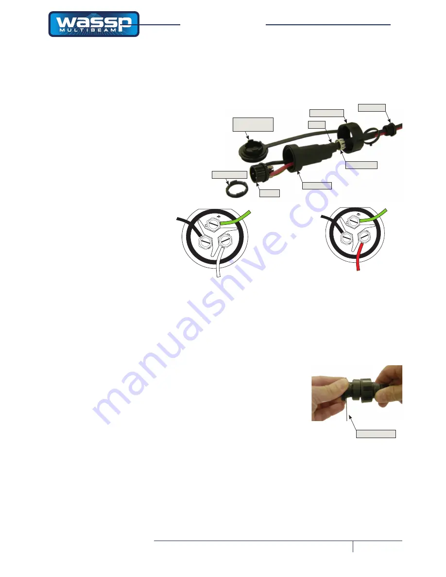
Transmitter Cable Socket Assembly

If the transmitter cable socket needs to be disassembled, use the locking ring 

tightening tool supplied with the BTxR to loosen the locking ring. To assemble the 

3-pin sealed plug:

•  Gland Nut.
•  Gland Cage.
•  Gland.
•  Main Body.

Gland Cage

Gland

Gland Nut

Locking Cap

Main Body

Socket

Locking Ring

Locking Ring 

Tightening Tool

E

L

N

RED

GREEN

BLACK

1) 

Push the following parts over the transmit-

ter wires:

2) 

Attach the RED or WHITE wire to 

L

, the 

BLACK wire to 

N

, and the GREEN wire 

to 

E

 on the socket and tighten all three 

screws.

3) 

Push the socket into the main body, mak-

ing sure that the flat on the socket locates 

into the flat on the main body.

4) 

Using the tightening tool, screw the locking 

ring into the front of the socket until tight.

5) 

Push the gland, gland cage, and gland nut 

into the main body as far as it will go and 

tighten the nut securely.

Tightening Tool

Installation Manual

E

L

N

WHITE

GREEN

BLACK

Later cable colour code                                      Early cable colour code

Содержание WMB-160F

Страница 1: ...Doc P N WSP 009 002 Version V2 3 Issue Date July 2014 WASSP F SERIES INSTALLATION MANUAL WMB 160F and WMB 80F...

Страница 2: ...Figures 7 and 11 V2 1 27 June 2012 V52 updates V2 2 4 July 2014 V52 5 Updates V2 3 Document Revision History Safety Notices The installer of the equipment is solely responsible for the correct install...

Страница 3: ...Cable Gland 18 Cable Gland Assembly RJ 45 Type Connectors 20 Repairing Replacing an RJ 45 Connector 21 Mounting Instructions Transceiver 22 Transceiver Installation Considerations 22 Transceiver Insta...

Страница 4: ...Commissioning Step 11 Side Lobe Levels 54 Sea Trial Commissioning Step 12 Patch Test Roll 55 Sea Trial Commissioning Step 13 Sound Speed 56 Sea Trial Commissioning Step 14 Beam Width Reduction 57 Sea...

Страница 5: ...presented in a user friendly mouse controlled Windows based operating system The system can output data to plotting software packages For optimal performance roll heave pitch heading and position inp...

Страница 6: ...ing at a frequency of 160 kHz provides high sea floor definition 2 D and 3 D zoom 2 D zooming from 250 m out to 3 km 3 D zooming from 10 m out to 1 km Depth and sea floor coverage Sea floor coverage i...

Страница 7: ...ssue Date July 2014 Installation Manual www wassp com System Configuration Figure 1 shows a fully functional WMB 160 80F Sonar system Figure 1 Overview of a Fully Functional WMB 160 80F Sonar System w...

Страница 8: ...ealing the transducer should be designed and constructed by a reputable shipyard to suit the size and contours of the hull of each individual vessel This must be sized and constructed accurately The s...

Страница 9: ...uired to mount Shuttle PC Cable Clamp WSP 201 020 1 Clamps transducer cable Keyboard WSP 002 002 1 Trackball WSP 002 001 1 Ethernet cable WSP 002 020 1 15 m NMEA optocoupler WSP 002 004 1 NMEA 9 pin c...

Страница 10: ...ard of lifting strakes as these create acoustic noise The transducer must always remain submerged even when the boat is rolling pitching or planing at high speed A practical choice would be somewhere...

Страница 11: ...ion must be such that beam is clear of hull Figure 3 Through hull Compact Type Transducer Mounting Mounting Methods The above mounting example is provided as a guide WASSP Ltd recommend that a reputab...

Страница 12: ...unt the transducer to the hull Note Use the sizes in this diagram to assist in the manu facture of the sea chest and transducer backing plate TOP VIEW SIDE VIEW Drawing not to scale All sizes in milli...

Страница 13: ...275 8 x 4 mm holes Footprint of Computer Mounting Bracket Computer Mounting on Bracket 6 32 UNC Screws Rear Case Screws 190 187 203 290 250 Figure 6 Shuttle XPC Computer Outline Shuttle Computer Mount...

Страница 14: ...bracket and UPS If installing the UPS carefully read the supplied manufacturer s quick start guide and install and operate the UPS accordingly 1 Install the UPS indoors in a controlled environment wh...

Страница 15: ...Installation Manual www wassp com Figure 8 230 V AC UPS Mounting Bracket Outline and Dimensions 200 145 SIDE VIEW UPS on Mounting Bracket with Velcro Holding Strap 20 92 5 20 185 10 260 10 TOP VIEW M...

Страница 16: ...line and Dimensions Figure 9 shows the physical dimensions of the optional WASSP Ltd supplied 24 V DC Power Supply Unit PSU The hole centres on the mounting bracket can be used as a template for insta...

Страница 17: ...enter the inverter 2 COOL The ambient air temperature should be between 0 C and 33 C the cooler the better 3 SAFE Do not install the inverter in a battery compartment or other areas where flammable f...

Страница 18: ...an as much of the soapy water off as possible to ensure the packing ring grips the cable when pressure is applied by the gland nut Tighten the gland nut by hand until secure With the vessel in the wat...

Страница 19: ...Manual www wassp com TRANSDUCER CABLE GLAND NUT STEEL WASHER GLAND PACKING RING GLAND PIPE HULL PLATE GLAND PIPE FLANGE LOCK SCREW Cut away of gland GLAND LOCK NUT LOCK PLATE GASKET ABOVE HULL GASKET...

Страница 20: ...nsmit connection To fit the RJ 45 connectors and cable through the gland no special preparation is required The BTxR Transceiver cable end has the RJ 45 connectors fitted with staggered cable lengths...

Страница 21: ...sducer cable follow standard CAT5 colour codes but the RJ 45 plug wiring is specific to the BTxR and does NOT conform to T568A or B Pin 8 Pin 1 S c r e e n d r a i n w i r e B l u e a n d B l u e W h...

Страница 22: ...and mounting clearances 1 Using the mounting holes on the mounting flanges secure the transceiver to the mounting surface 2 Connect the following cables to the faceplate end cover See Interface Conne...

Страница 23: ...ening Tool E L N RED GREEN BLACK 1 Push the following parts over the transmit ter wires 2 Attach the RED or WHITE wire to L the BLACK wire to N and the GREEN wire to E on the socket and tighten all th...

Страница 24: ...24 Volt Power Supply Socket CAT5 Ethernet Cable Socket Figure 14b RJ45 type Transceiver Cable Clamp The transceiver cable MUST be fit ted with the supplied cable clamp to prevent strain on the RJ 45...

Страница 25: ...n closed radome housing An Interface Unit See Satellite Compass Software Set Up for a detailed set of procedures For full details on mounting the units of the SC 30 see the Furuno documentation suppli...

Страница 26: ...ading Satellite Compass SC 30 optional for GPS Pitch and Roll inputs Transceiver WMB BTXR Faceplate End Cover Ethernet CAT5 Crossover Cable WMB BTXR TCPCable Earthing Strap Connector TCP IP 12 50 35 H...

Страница 27: ...es accepted by the system are ATT GGA GGL HDT HDG HVE RCD RMC VTG ZDA PSXN PFEC GPatt PFEC GPhve PASHR If an SC 30 with IF NMEASC Interface Unit is installed route the NMEA information to the computer...

Страница 28: ...ATT True heading pitching rolling Furuno proprietary sentence GGA Global positioning system GPS fix data GLL Geographic position Latitude and Longitude GNS GNSS fix data HDM Magnetic Heading obtained...

Страница 29: ...www wassp com Shuttle PC The WASSP system is supplied with a Model SG31 Shuttle PC Figure 19 Shuttle PC Front View DO NOT USE DVI Port Figure 20 Shuttle PC Rear View connections X Note The Shut tle P...

Страница 30: ...and firmware against the versions in your system Depending on the versions of software and firmware installed in your system the install program has a number of responses If while the system check is...

Страница 31: ...is to create a desktop icon Click Next The default is to save the software in C Progams WASSP Ltd WASSP If you require this to be saved elsewhere Browse and select location Click Next The folder alre...

Страница 32: ...he BTxR selected ensure it is tuned on and connected Click Finish 8 9 10 1 1 Right click the Serial Transfer Task icon on the Windows Task bar 2 Click Setup The Serial Transfer Task box opens 3 In the...

Страница 33: ...nual www wassp com If you get the following error the BTxR is either not turned on or not connected Turn on connect the BTxR and click Retry The installation will continue The BTxR Software will check...

Страница 34: ...r or transceiver If you attach a dongle after running the WMB 160 80F software program restart the WMB 160 80F program For a complete description of the WMB 160 80F Multi beam Sonar System program fun...

Страница 35: ...sor drop down list and select Furuno SC50 from the list The SC50 setting is used for both SC50 and SC30 6 Click the Motion Sensor drop down list and select Furuno SC50 from the list The SC50 setting i...

Страница 36: ...68 2 Click the Screen Saver Tab 3 Select Screen Saver None 4 Click the Power button 5 Configure the power management settings so the monitor and hard disks never turn off automatically 6 Click OK to c...

Страница 37: ...f NMEA and WMB 160 80F set up and communication port settings To open the Serial Task Transfer box and enter the NMEA and WMB 160 80F set up and communication port settings 1 1 Right click the Serial...

Страница 38: ...014 Installation Manual www wassp com Figure 23 WASSP WMB160 80F Settings Tabbed Page With all units installed their cables connected all software installed and the computer and satellite compass runn...

Страница 39: ...y changes you make may not be recoverable To enter the system configuration utility See Figure 24 1 Click the System Configuration Utility button The system configuration utility window opens 2 Click...

Страница 40: ...Page 40 of 68 Doc P N WSP 009 002 Version V2 3 Issue Date July 2014 Installation Manual www wassp com Figure 24 Technician Utility Showing Options Available with a Technician Dongle Connected 1 2 3 4...

Страница 41: ...be on The effects of not having this on when it should be are multiple torch lights of noise appearing down the sonar display like the noise shown in Figure 31 except more than one line Request Calibr...

Страница 42: ...les reduction in interference caused by other acoustic devices such as sounders It also provides some noise filtering It is recommended that the interference filter be left selected ON on if you have...

Страница 43: ...so remove bottom detections which intersect with interfering pulses Single Beam IF This is a new filter just for the single beam display It will remove interfering pulses from the sonar data NOTE this...

Страница 44: ...y invalidate the commissioning procedure Commissioning procedures are divided into two sets Dockside Tests Sea Trials Dockside Tests The first part of the commissioning procedures requires a number of...

Страница 45: ...sp com Figure 27 Ship Measurements Diagram R Tx X axis GPS X Tx X GPS GPS Tx R GPS Z Tx Z Tx Depth Displacement Z axis Y axis R Tx GPS Y Tx Y GPS Stern Negative Bow Positive Reference Sky Negative Ref...

Страница 46: ...to the right of the bars controls the gain of the display UP increases the gain while DOWN decreases the gain See Figure 28 Use the slider bar on the side of the box to adjust the lower 52 bars so tha...

Страница 47: ...gure 28 shows a typical transmission pulse with a reasonably weak bottom return which is a typical shape When functioning correctly all 26 channels should display very similar information to each othe...

Страница 48: ...not known set the transducer number to 1 or 200 depending on which gives the best sea floor results Having the incorrect value will result in a strange mirror effect see Figure 28 Figure 30 Sonar Vie...

Страница 49: ...nd with all other sounding devices off Gain Control Knob Range Control Knob Figure 31 System with Significant Electrical Noise Check the centre line of the Sonar display for a consistent signal or a c...

Страница 50: ...m Figure 31b WASSP sonar display with low electrical noise Figure 31c Sonar display with one very noisy channel can make the Sonar diffi cult to use This particular failure might have been detected by...

Страница 51: ...of the contour view screen will display with a WHITE heading line This line should be stable if not ensure TMG is not selected as Heading Type as this is not appropriate for mapping Fill in the Vesse...

Страница 52: ...least 20 metres of water Commissioning Step 8 Tide Configuration Use the System Configuration Utility Tides page to enable Tide Correction Tide calculation requires Position and Time if these are not...

Страница 53: ...hip Setup Options Sensor Values tab and record the new value below See Figure 33 Swap Array Selected Yes No Sea Trial Commissioning Step 10 Roll Correction Polarity Watch the sonar view carefully when...

Страница 54: ...east 2 Open the Advanced Options Controls and move them so that you can adjust the Minimisation while watching the sonar display area above the sea floor change Look at the pictures below in Figure 34...

Страница 55: ...System Configuration Utility click on the box marked Patch Test and follow the instructions on the bottom of the screen 4 Drive the vessel at a constant heading for a few hundred metres until the Pat...

Страница 56: ...putation method to Manual in the Ship Setup Sound Speed Tab 3 Find a section of sea floor that is known to be flat preferably 20 100m deep 4 Cross over the section of sea floor and adjust the sound sp...

Страница 57: ...the Sonar display as perpetually weak echoes on the outer beams Failure to reduce the beam width will introduce false data on the outer edges into the backscatter and depth maps Figure 37 Frilly edges...

Страница 58: ...en if the value for GPS delay was positive at the time the test was undertaken The formula below outlines this process the delay adjustment is added to the current GPS Time Delay value on the Ship Set...

Страница 59: ...definition The Sidescan Gain control can be varied at any time Changing the Sidescan Gain Threshold will cause a big step in the Sidescan and the old data will not be reprocessed to conform to this g...

Страница 60: ...recorded during this Mapping as the data can be analysed in closer detail at a desk and can be compared to any subsequent data received from the vessel and may help isolation of a post commissioning...

Страница 61: ...omputer s USB port and click Retry c Turn on the satellite compass according to the manufacturer s instructions STATUS POWER You can click Cancel and run a demo file from the System Configuration Util...

Страница 62: ...Quit the WMB 160 80F program When you have completed your profiling operations a Click the MODE button to set the transceiver to standby b Click Close on the task bar The Exit System box appears c Cli...

Страница 63: ...Figure 16 WMB 160 80F Transceiver Interface Connections for details Software installation and settings See procedures for Checking Software Installation in the WASSP Operator Manual NMEA data sentenc...

Страница 64: ...em does not have provision for variance in the Motion Time Lag from the default values shown in the Sensor Tab at this time w d 2 a d tan a d 2w If object moves as above the sign is negated otherwise...

Страница 65: ...tallation Manual www wassp com 160 kHz Compact Transducer Dimensions The drawing below gives the overall dimensions of the WASSP WMB 160 80F Compact Transducer The recommended cut out dimensions for a...

Страница 66: ...n V2 3 Issue Date July 2014 Installation Manual www wassp com 80kHz Transducer Dimensions The drawing below gives the overall dimensions of the WASSP WMB 80F Sea Chest Type Transducer The recommended...

Страница 67: ...ft 500 m Stabilisation Roll 30 depending on sensor Interface Inputs NMEA sentences GGA GGL HDG HDT MTW VTG RMC ZDA PSXN PFEC Gpatt PFEC Gphve Power Supply Transceiver Computer 24 V DC 150 W 230 V AC 5...

Страница 68: ...erface Inputs NMEA sentences GGA GGL HDG HDT MTW VTG RMC ZDA PSXN PFEC Gpatt PFEC Gphve Power Supply Transceiver Computer 24 V DC 70 W 230 V AC 50 to 60 Hz inverter from 24 V DC ships supply Environme...

Отзывы: