12
Section 4
1) Wire Feeder structure:
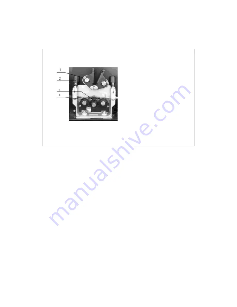
Wire Feeder structure, as Figure 6:
Figure 6 :-
(1) Pressing Handle
(2) Wire Pressing Roller
(3) Driving Gear
(4) Wire Feed Roller
2) Wire Feeder Roller and Installation
There is a scale for wire feeding pressure on the Pressing Handle, Different materials and
sizes of the wires are corresponding to different pressures value, refer to Table 1 and
Figure 6 and Figure 7 for detail. The data in the table is only for reference, the actual
pressure regulator
norms must be adjusted based on torch model, cable length, type of welding torch,
welding wire type and size.
• Type 1 for hard wire, such as carbon steel wire, stainless steel wire.
• Type 2 for soft wire, such as Aluminum wire and AL alloys wire, copper wire and
cooper Alloy wire.
• Type 3 for flux cored wire.
Regulating the pressure of feeding rollers with the pressure handle, ensure the wire go
through the guiding tube smoothly, and there should be a bit brake force where the wire
come out from the conductive tip to avoid the wire feed rollers skidding.
Note: Too much pressure will cause wire crushed, and the wire coating will be damaged,
and it will cause feed rollers wear out, and increase the wire feeding resistance


