background image

4

Wall Heating - 

Quick Install Guide

Quick Install Guide -

 The full installation instructions in this 

manual must be followed�

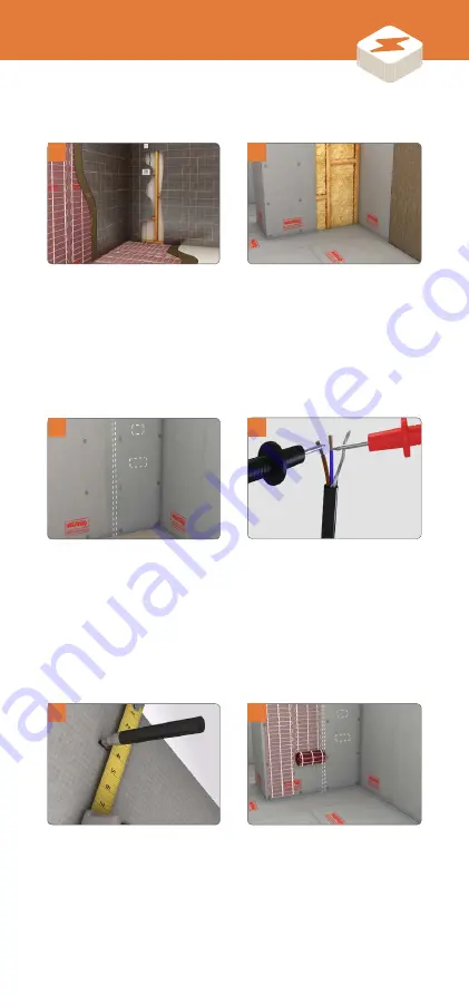
   We recommend installing 

Warmup insulation boards for 

optimum performance.

  Test the resistance of the 

heater ensuring it is within the 

range set out in the Reference 

Resistance Band tables.

  Cut, turn and affix the mat 

to the substrate using self-

adhesive mesh or double 

sided tape.

  Make electrical provision for 

the heater (30 mA RCD, 35 mm 

deep electrical back boxes, 

trunking).

  Mark on the boards where any 

penetrating fixtures are likely 

to be such as, mirrors, shower 

screens, towel rails etc. 

  The cable should be installed 

40 mm in from the edge of the 

heated area or penetrations 

through the substrate.

1

3

5

4

2

6

Содержание StickyMat 3D

Страница 1: ...1 StickyMat 3D Installation Manual Electric Heating System Technical Helpline 0345 345 2288 ...

Страница 2: ...up Natural Language Programming Programming that speaks your language Please scan the QR code for more information The world s best selling floor heating brand Over 2 million installations in more than 60 countries EasySwitch Always on the best tariff automatically SmartGeo Smarter geo fencing Reduce energy usage by up to 25 ...

Страница 3: ...ting system has been designed so that installation is quick and straight forward but as with all electrical systems certain procedures must be strictly followed Please ensure that you have the correct heater s for the area you wish to heat Warmup plc the manufacturer of the Warmup StickyMat 3D System accepts no liability expressed or implied for any loss or consequential damage suffered as a resul...

Страница 4: ...t out in the Reference Resistance Band tables Cut turn and affix the mat to the substrate using self adhesive mesh or double sided tape Make electrical provision for the heater 30 mA RCD 35 mm deep electrical back boxes trunking Mark on the boards where any penetrating fixtures are likely to be such as mirrors shower screens towel rails etc The cable should be installed 40 mm in from the edge of t...

Страница 5: ...OT install the thermostat on the same wall as the heater Channel a groove in the boards for the coldtail termination joints enabling them to fit flush with the top of the heater DO NOT tape over these joints Install the sensor probe centrally between two runs of the heater Lay the adhesive and tiles over the system Use flexible grout when grouting If a plaster finish is required apply a minimum co...

Страница 6: ...chen units etc are likely to be The cable should be installed 40 mm in from the edge of the heated area or penetrations through the floor Make electrical provision for the heater 30 mA RCD 35mm deep electrical back boxes trunking We recommend installing Warmup insulation boards for optimum performance Test the resistance of the heater ensuring it is within the range set out in the Reference Resist...

Страница 7: ... levelling compound and not exposed Use flexible grout when grouting Connect your Warmup thermostat Cut turn and affix the mat to the subfloor using self adhesive mesh or double sided tape Any loose heating cable removed from the mesh must be installed at no less than 50 mm intervals and tab taped in place Test the resistance of the heating cable after installation and check against the previous v...

Страница 8: ...f your Warmup heating installation 30 mA Residual Current Device RCD required as part of all installations Digital Multi meter required for testing the resistance of the heater and sensor probe Electrical tape to secure the sensor probe Electrical housing back boxes and junction boxes Electrical trunking conduit for housing the power leads Flexible tile adhesive and flexible grout Staple gun ...

Страница 9: ...entilated space beneath it to allow heat flow into the room Ensure that during the course of the installation no damage is caused to the heater by falling or sharp objects Cut or shorten the heating element at any time Leave surplus heater rolled up under units or fixtures use the correct size heater Connect two heaters in series only connect heaters in parallel Attempt a DIY repair if you damage ...

Страница 10: ...the circuit can handle the additional load NOTE A junction box is required if more than two heaters are being connected to a single Warmup thermostat NOTE When conducting an insulation resistance test on the supply to the thermostat the thermostat and heaters must be isolated or disconnected Warmup Thermostat 13 amp fused spur or RCD spur supplying power to the thermostat Floor Sensor 300 mm into ...

Страница 11: ...side of wet rooms in the adjacent connected room in circumstances where it is not practicable to install the thermostat within the wet room When installed in this way using only the sensor probe to control the heating it is not possible to directly control the air temperature only the surface temperature All electrical connections must conform to the current BS 7671 National Wiring Regulations Fin...

Страница 12: ...face of the Warmup insulation board For uneven walls increase to a 20 mm trowel Push firmly onto wall staggering the joints NOTE For full instructions please refer to the Warmup Insulation Board manual RECOMMENDED SOLID WALL RECOMMENDED STUD WALL 1 Wall Finish 2 Flexible tile adhesive or plaster 3 Warmup StickyMat 3D 4 Warmup Insulation Board 5 Flexible Tile Adhesive 6 Solid Wall 1 Wall Finish 2 F...

Страница 13: ...or optimum performance it is recommended that you use Warmup Insulation Boards beneath Warmup StickyMat 3D The insulation will improve the systems response to heating demand saving energy and reducing running costs RECOMMENDED BUILD UP 1 Floor Finish 2 Flexible tile adhesive or levelling compound 3 Warmup StickyMat 3D 4 Warmup Insulation Board 5 Flexible Tile Adhesive 6 Subfloor 4 1 2 3 5 6 LOW PR...

Страница 14: ...r probe This will cause overheating and will damage the cable NOTE The heater should not be installed on irregular surfaces such as on stairs Before you begin Heating cables cannot be installed across expansion joints within the floor Where a heated floor is divided by expansion joints individual cables should be used to heat each area The cold tail may cross the expansion joint within a 300 mm lo...

Страница 15: ... plan has the proper room dimensions and that you have the correct size and proper number of mats Mats should run backwards and forwards between walls and obstructions as shown in the examples NOTE When laying two or more heaters ensure all coldtails reach the thermostat Modifying the Mat Example installation diagrams Thermostat Thermostat Thermostat 1 2 3 1 2 3 Thermostat Thermostat Thermostat Wa...

Страница 16: ...istance Before column of the control card supplied as part of this installation guide Stop installation immediately and contact Warmup if its resistance falls outside the range set out in the Reference Resistance Band table Secure the cold tail using tabs of electrical tape Cut a section in the board for the manufactured joint so that it sits at the same height as the heater DO NOT tape over the m...

Страница 17: ...heater DO NOT tape over the termination joint it must be in direct contact and fully embedded within the tile adhesive plaster being laid over the heating cable 6 7 Begin laying the mat cutting the mesh and turning the mat to fit the wall area Secure the mat to the boards using the self adhesive mesh or double sided tape If required the mat can be stabled to the boards using a staple gun NOTE DO N...

Страница 18: ...ine with the Resistance Before reading previously taken Stop installation immediately and contact Warmup if its resistance has changed significantly or if it falls outside the range set out in the Reference Resistance Band table 9 Wall Applications Step 4 Install StickyMat 3d ...

Страница 19: ...e checked against required operating conditions Tile Finish Plaster finish Substrate Flexible tile adhesive For Warmup Insulation Boards Warmup Insulation boards Recommended 3 mm Warmup StickyMat 3D Flexible tile adhesive Wall finish Ceramic Tile _Tile pdf 1 18 06 2019 11 57 11 Substrate Flexible tile adhesive For Warmup Insulation Boards Warmup Insulation boards Recommended 3 mm Warmup StickyMat ...

Страница 20: ...ible tile adhesive using a notched trowel Take care not to damage or dislodge the heating cable After laying the first tile remove and ensure the tile is getting a full coverage of adhesive from your application Ensure the width of the grout line is in line with the manufacturers instructions for the size and type of tile being used Tiles must not be removed once the adhesive has set doing so will...

Страница 21: ...ered wall rather than a tile finish you MUST lay a minimum 8 mm base coat of plaster over the heater first followed by a final layer of plaster not less than 2 mm thick You must ensure that all heating cables including both coldtail and termination joint are completely covered 1 2 NOTE If installing anything over the plaster finish such as textile tiles the combined resistance of both plaster and ...

Страница 22: ... appropriate smoothing or levelling compound should be applied Mark out the floor with a permanent marker showing where fixtures and other unheated areas are going to be Measure and record the resistance of the heating cable in the Resistance Before column of the control card supplied as part of this installation guide Stop installation immediately and contact Warmup if its resistance falls outsid...

Страница 23: ...ng the self adhesive mesh or double sided tape Follow the installation layout as in Step 3 to complete the heater placement DO NOT install the heating cable in temperatures less than 10 C To install the mat in awkward areas the heating cable can be removed from the mesh and fixed in place with tabs of tape taking care to remove air cavities Maintain the minimum 50 mm spacing between parallel heati...

Страница 24: ...the resistance of the floor sensor and record it on the control card If it s resistance is outside the prescribed range contact Warmup DO NOT tape over the floor sensor tip it must be in full contact with the heated tile adhesive or levelling compound Install the floor sensor at least 300 mm into the heated area it will be controlling It should be located centrally between parallel runs of heating...

Страница 25: ...d 3 mm Warmup StickyMat 3D Flexible tile adhesive Floor finish Ceramic Tile Subfloor Flexible tile adhesive For Warmup Insulation Boards Warmup Insulation Boards Recommended 3 mm Warmup StickyMat 3D 10mm Self Leveling Compound Floor finish Once the StickyMat 3D system has been installed we recommend laying a 10 mm layer of self levelling compound over the heater which is suitable for use with unde...

Страница 26: ... trowel Take care not to damage or dislodge the heating cable If using tiles smaller than 90 mm cover the installation with levelling compound first After laying the first tile remove and ensure the tile is getting a full coverage of adhesive from your application Ensure the width of the grout line is in line with the manufacturers instructions for the size and type of tile being used Tiles must n...

Страница 27: ...u are planning to install wood carpet or vinyl over the heater you MUST lay a minimum 10mm levelling compound over the heater You must ensure that all heating cables are completely covered It is important that the levelling compound is suitable for use with underfloor heating 1 1 NOTE Before installing the floor finish its suitability for use with underfloor heating and its maximum operating tempe...

Страница 28: ...regulations The heater power cable consists of conductors coloured brown live blue neutral and earth braid If you are installing more than two heaters on a single Warmup thermostat a junction box will be required These should be connected in accordance with current wiring regulations by a qualified Part P electrician THERMOSTAT WIRING 1 Power Supply Cable 230 V AC Wired via 30 mA RCD spur supplyin...

Страница 29: ...neer Service Call required Please contact Warmup for more information Can you hear the relay click on when the thermostat is calling for heat Measure the output voltage Is there 230 V on the load side when the stat calls for power Conduct a resistance insulation resistance test Do the figures match the control card and or reference resistance bands Is there an earth fault between live earth or neu...

Страница 30: ...d Please contact Warmup for more information Conduct a resistance insulation resistance test Do the figures match the control card and or reference resistance bands Is there an earth fault between live earth or neutral earth Are the connections on the back of the thermostat made in line with the wiring diagram Rewire as per the wiring diagram Test RCD NO YES YES YES NO NO ...

Страница 31: ...rs walls to up to 9 C above the design room air temperature which is typically 29 C Delicate floor finishes such as vinyl and some timbers may be limited to 27 C Our hand and foot temperature is normally similar to this at around 29 32 C so the heated floor will feel slightly cooler than touching your own hands together If you wish to raise the temperature such that it feels warm it is permissible...

Страница 32: ... is also lower than desired supplementary heating may be required to overcome the room heat losses If access is available to the substrate installing insulation within the floor wall will reduce the amount of heat lost through the floor wall 6 Floor coverings such as carpets underlays and timber are thermally resistive and will reduce the achievable floor surface temperature They may also require ...

Страница 33: ...s greater than 500 MΩ or infinite if the meter cannot read this high Insulation resistance test Set an insulation resistance tester to 500 V DC Measure the resistance across the live brown and neutral blue wires to the earth green yellow or metallic braid wire Ensure the measured resistance is showing greater than 500 MΩ to indicate a pass NOTE Due to the high resistance of the heating element it ...

Страница 34: ...34 Layout Plan NOTE Draw a plan showing the layout and location of the heating cable s ...

Страница 35: ...ting element Ensure that the entire heating element s including the joints are installed within the layer of tile adhesive levelling compound or plaster DO NOT tape over the joints or heating cable as this may insulate them causing them to fail The heating element must be used in conjunction with a 30 mA RCD Heater Model Resistance Before Resistance After Insulation Resistance Pass Sensor probe re...

Страница 36: ...der this guarantee which does not affect your statutory rights Such cost does not extend to any cost other than direct cost of repair or replacement by Warmup and does not extend to costs of relaying replacing or repairing any floor wall covering or floor wall If the heater fails due to damage caused during installation or tiling this guarantee does not apply It is therefore important to check tha...

Страница 37: ...ed heaters carry a 5 year warranty only Under no circumstances is Warmup responsible for the repair or replacement of any tiles floor covering which may be removed or damaged in order to affect the repair ii The SafetyNet Installation Guarantee does not cover any other type of damage misuse or improper installation due to improper adhesive or subfloor conditions Limit of one free replacement heate...

Страница 38: ...ULATION ETFE MIN TEMPERATURE INSTALLATION 10 C CONNECTION 3 m LONG COLDTAIL CONNECTION Technical Specifications StickyMat 3d 200W m PRODUCT CODE HEATED AREA m POWER W LOAD A RESISTANCE Ω 2SMFW 0 5 0 5 100 0 43 529 0 2SMFW 1 1 200 0 87 264 5 2SMFW 1 5 1 5 300 1 30 176 3 2SMFW 2 2 400 1 74 132 3 Mat size guide REFERENCE RESISTANCE BANDS Ω 502 6 555 5 251 3 278 7 167 5 185 1 125 7 138 9 ...

Страница 39: ...39 ...

Страница 40: ...4 Tudor Estate Abbey Road London NW10 7UW Web www warmup co uk Email uk warmup com Tel 0345 345 2288 Fax 0345 345 2299 The WARMUP word and associated logos are trade marks Warmup Plc 2019 Regd Nos 1257724 4409934 4409926 5265707 E OE Warmup IM StickyMat3D v1 2 2019 06 18_Online ...

Отзывы: