background image

14 June 2016 

Due to continued product improvement, Warmington Ind LTD reserves the right to change product specifications without prior notification. 

All Dimension are in mm……..Copyright ©  

17 

PROCEDURE FOR THE TEST AND COMISSIONING OF YOUR DECORATIVE FIRE.


Ensure Gas Supply and  the Power Supply (caution 240V) to the Unit. 

 

Refer to Data Plate  on this Specification for settings. The Data Plate is attached to the under carriage of 
the Burner . 


 

Remove Front Grate ensure the CAT5 cable to the Control Receiver is still connected. 


 

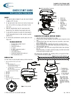
Loosen the Jet Test point and attach manometer (Digital is preferred).  The Test Point is on the Right 
Hand Side of the Gas Burner , as Shown Below . 


 

Light Appliance, adjust to High Flame setting and check pressure, adjust to Low Flame and check pres-
sure. 


NOTE : If setting the Pressure is required it is to be carried out by a certified Gas Fitter.


 

If adjustments are necessary, remove the cap . The Pressure Adjustment Screw and Nut are on the 
Front Side of the Gas Control Valve (shown in Diagram 

in this specification) and are 

Factory 

set. 


High Pressure Setting

: Set the modulator to Maximum Condition. Screw in Nut A to Increase the Outlet Pres-

sure then screw Nut A out to Decrease the Pressure to the desired settings . Use 10mm spanner. 


Low Pressure Setting: 

Turn Off the Power to the Modulator (by disconnecting the Modulator Harness Connec-

tion at the Valve - See Wiring Diagram in Page 17 .) and, keep Nut A stationary . Use a screwdriver to screw in 
Screw B to Increase the Pressure and Screw it Out to Decrease the Pressure . Carefully replace the Modulator 
Plastic Cap . 


WARNING: 

To ensure the Correct Operation of the Modulator it is necessary that the Plastic Cap is returned to 

its original location . 
 

Gas Test Nipple 
for SG / EG Fires 

Содержание SG 700

Страница 1: ...and tested to comply with NZS 4558 int 2013 Decorative gas log and other fuel effect appliances Keep these instructions for further reference Ensure that you have the correct and current installation...

Страница 2: ...TIFIED GASFITTER OR CERTFIED NZHHA SFAIT INSTALLER WHAT S SUPPLIED WHEN ORDERED LEAVE MANUAL WITH THE CUSTOMER ONCE INSTALLED INSTALLER OWNER PLEASE KEEP THESE SPECIFICATIONS FOR FUTURE REFERENCE Supp...

Страница 3: ...x 100mm Vents should be fitted 1 at the Top of the alcove and 1 at the base of the Alcove to allow air flow Note Clean and touch up paint on the fire and cover if necessary Stage 3 Finishing Procedur...

Страница 4: ...th H 395 395 395 395 395 395 Fascia Width L 1060 1260 1410 1560 940 860 Fascia Height M 680 680 680 680 680 680 Fascia Section N 80 80 80 80 80 80 Hearth Width O 1100 1180 1300 1500 1550 1800 Hearth P...

Страница 5: ...ase and at the Top Hebel Cell Firebox Fiberglass Reinforced Mesh 2mm Non Combustible Latex Based Plaster Water Proof Non Combustible Important Note NO Combustible Material to be used below the measure...

Страница 6: ...kPa 2 75 kPa 2 75 kPa 2 75 kPa 2 75 kPa Nominal Injector Size mm 2 X 1 3mm 2 X 1 4mm 4 X 1 1mm 4 x 1 2mm 2 X 1 2mm 2 X 1 1mm Burner Pressure High Kpa 2 5 2 5 2 5 2 5 2 5 2 5 Burner Pressure Low Kpa 0...

Страница 7: ...LINTH CONSTRUCTION DETAILS Note If Solid Plastering the Heat Cell Structure it is recommended to use a Fibreglass Mesh with a Latex Based Plaster to minimise the chance of the Solid Plaster cracking S...

Страница 8: ...600 600 Heat Cell Clearance width J 1210 1210 1210 1610 1610 1610 Heat Sensitive Zone R 1700 1700 1700 1700 1700 1700 IMPORTANT NOTE ALL WARMINGTON FLUELESS GAS FIRES ARE TO BE REBATED INTO ITS ENCLOS...

Страница 9: ...o change product specifications without prior notification All Dimension are in mm Copyright 9 GAS SUPPLY ELECTRONICS LOCATION Firebox SG EG 700 SG EG 780 SG EG 900 SG EG 1100 SG EG 1250 SG EG 1500 Fr...

Страница 10: ...r of the Installation Cavity through the hole provided A Flare Nut is provided on the Burner for Gas Connection to the Appliance TO THE INSTALLER GAS FITTER ELECTRICIAN FITMENT OF BURNER Burner may be...

Страница 11: ...ttered to achieve best Visual Effect Fit Burner Grate by sliding R L Side Metal Pins on Grate into Holes Located on Burner Side Plates as shown below 2 Top Row Slide R LH Grate Pins into Holes located...

Страница 12: ...o light all the way across Once the flame is established adjust to the desired setting and close the cover To shut down Open the cover by pulling it outwards Turn the control ignition switch to PILOT...

Страница 13: ...e Control Valves are Factory Set but may require adjustment onsite Turn Appliance Off Remove Front Plastic Cover on Igniter Pull Cover to Slide off Unscrew Test Nipple on the Burner Manifold fit the T...

Страница 14: ...bserve the following precautions associated with any heating appliance or open fire Do not cover or restrict the fireplace upper or lower vents in any way as this may result in a build up of hazardous...

Страница 15: ...s Switched Off due to Power Failure In the circumstance of a Power Failure the Remote Control System will return to the default settings which is a Low Flame and the Fan Turned Off If the Gas Fails to...

Страница 16: ...the Power LED will start flashing and after 30 minutes the appliance will Shut Off Automatically By pressing the Timer Button again within the 30 minute period this will reset the Timer and the power...

Страница 17: ...TE If setting the Pressure is required it is to be carried out by a certified Gas Fitter If adjustments are necessary remove the cap The Pressure Adjustment Screw and Nut are on the Front Side of the...

Страница 18: ...fied that the Appliance is working correctly fit the Front Panel Assembly back to the Gas Burner NOTE Ensure you peel the Protective Plastic Coating from any Stainless Steel components if fitted All B...

Страница 19: ...nd LTD reserves the right to change product specifications without prior notification All Dimension are in mm Copyright 19 REMOTE IGNITION EG GAS FIRE WIRING DIAGRAM Modulator Harness Connections Note...

Страница 20: ...t be serviced annually and any service operation must be carried out by a qualified service person WARNINGS WARNING ANY MODIFICATION OF THE APPLIANCE THAT HAS NOT BEEN APPROVED IN WRITING BY THE TESTI...

Отзывы: