M40
7 / ENGLISH
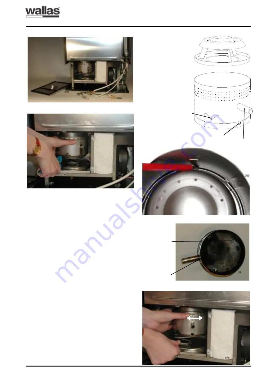
Fig. 12 shows the burner parts of M40. De-
tach the heat radiator by pressing the locking
tongue towards the burner cylinder wall and by
inclining the heat radiator. Fig. 13.
Crust is mainly formed on the bottom of the
burner cylinder. Scratch the crust carefully off,
for example, by using a screwdriver. If neces-
sary, also clean the walls of the burner cylinder
and the heat radiator. It is advisable to replace
the bottom carpet in position when cleaning
the cylinder. Fig. 14. The bottom carpet acts
as a heat insulator of the burner cylinder du-
ring ignition, and consequently, the carpet must
be intact at least under the glow plug.
The burner is reassembled in the same way
as it was demounted, but in the reverse order.
When assembling the burner cylinder make
sure that the heat radiator is locked into its
position. To secure the locking, tap the burner
upside down, which makes the heat radiator
come off from its clamps, if it is not locked.
When installing the burner assembly move it
back and forth to make it settle tightly into the
heat exchanger. See the arrows in fig. 15. Turn
the burner to its position and push the spring
under the burner. Fig. 15.
Fig. 12: M40 burner parts.
Heat radiator
Burner cylinder
Temperature
sensor pipe
Fuel needle hole
Glow plug hole
Fig. 13: Detaching the heat radiator.
Fig. 14: Burner cylinder.
Bottom carpet.
Crust
Fig. 11: Detaching the burner.
Fig. 10: M40 burner chamber opened.
Fig. 15: Installation of the burner.
SERVICE INSTRUCTIONS
T0209


