


Touch Panel Standard Line
Properties 29
762-4xxx TP 600
Manual
Version 1.3.0
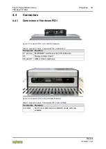
The connectors are located on the
bottom
. For details, see section “Properties” >
“Connectors.”
The operating mode switch with the settings RESET-STOP-RUN, the “CFG/RST”
button, the “SYS, RUN, CAN, H11, H22” LEDs and the “µSD” memory card slot
are located on the
left side
.
For details, see section “Properties” > “Connectors”
> “Display Elements” and > “Operating Elements”.
When the hardware is installed, the above-named function elements are not
accessible from the front.
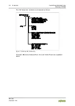
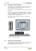
Figure 4: Other PIO2 Views (Example of 762-4204/8000-0001)
4.1.4
Other Views of the PIO3 Hardware
On the
back
there are four M4 threaded holes for VESA mounting, four fastening
clips, one grounding screw or lead and the device labeling. For details, see
section “Mounting” and “Properties” > “Labeling.”
The connectors are located on the
bottom
. For details, see section “Properties” >
“Connectors.”
The operating mode switch with the settings RESET-STOP-RUN, the “CFG/RST”
button, the “SYS, RUN, CAN, H11, H22” LEDs and the “µSD” memory card slot
are located on the
left side
.
For details, see section “Properties” > “Connectors”
> “Display Elements” and > “Operating Elements”.
Содержание Standard TP 600 762-4 Series
Страница 1: ...Manual Touch Panel Standard Line 762 4xxx xxxx xxxx TP 600 WAGO Touch Panel Version 1 3 0...
Страница 69: ...Touch Panel Standard Line Functions 69 762 4xxx TP 600 Manual Version 1 3 0 5 10 Booting Start Behavior...
Страница 70: ...70 Functions Touch Panel Standard Line 762 4xxx TP 600 Manual Version 1 3 0 Browser...
Страница 211: ...Touch Panel Standard Line 211 762 4xxx TP 600 Manual Version 1 3 0...


