16 Device Description
WAGO I/O System 750
750-637 Incremental Encoder Interfaces
Manual
Version 1.6.1
Public
3
Device Description
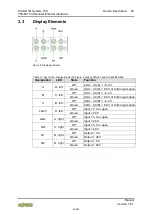
This module is an interface for different versions of incremental encoders with
various connections (RS-422, differential, single-ended).
The data width for the encoder module is 32 bits. Either the current counter
value, the latch value, the set value or the current rate can be shown in the
process data.
The table below provides an overview of the different versions and their
connections:
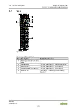
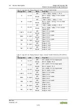
Table 4: Inputs/Outputs – Versions 750-637 and 750-637/000-003
Inputs/Outputs
A, /A, B, /B
Quadrature inputs, 24 V, RS-422
C, /C
Initial point input, 24 V, RS-422
Latch, Gate, Ref
Input, 24 V
N1, N2
Output, 24 V
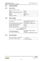
Table 5: Inputs/Outputs – Versions 750-637/000-001
Inputs/Outputs
A, /A, B, /B
Quadrature inputs, 24 V, differential
C, /C
Initial point input, 24 V, differential
Latch, Gate, Ref
Input, 24 V
N1, N2
Output, 24 V
Table 6: Inputs/Outputs – Versions 750-637/000-002 and 750-637/000-004
Inputs/Outputs
A, B
Quadrature inputs, 24 V, single-ended
C
Initial point input, 24 V, single-ended
Latch, Gate, Ref
Input, 24 V
N1, N2
Output, 24 V
A counter with quadrature decoder as well as a latch for the zero impulse can be
read or enabled by the control. The control can set the counter. Depending on
the operating mode, the counter value is added to the latch register on a positive
edge at the “C” or “Latch” input.
The rate (increments/ms) is automatically acquired and can also be transmitted to
the control as an alternative to the latch value.
A counter lock-out is possible using the “Gate” input. Input “Ref” can be used to
activate the initial point “C” function.
The cam outputs N1 and N2 indicate whether the counter value is within a
defined range of values. The range can be adjusted for each cam via the control
unit.


