background image

1

GM 2000 EAC

Item

Description

Part Number

1

Spray gun barrel

0179500

2

Bushing

0128336

3

Screw  countersunk

0179354

4

Type plate

9900962

5

Screw  flathead

9900810

6

O-ring

9971003

7

Knob, Air Adjustment

0179416

8

Trigger sleeve

0179396

9

Valve rod complete

0179254

10

Valve sealing element

0179236

11

O-ring

9971182

12

Compression ring

0179343

13

Seal

0179341

14

Sealing screw

0179342

15

Push-rod cap

0179340

16

Seal

0179395

17

Push-rod seal

0179339

18

O-ring

9971372

19

Valve push-rod

0179337

20

Valve rod

0179335

21

Valve rod spring guide

0179394

22

Compression spring

9994247

23

Adjusting element

0179253

24

Compression spring

9994248

25

Compressing element EAC

0179488

26

Locking nut

0179356

27

Double socket

9994627

28

Air hose

0128510

30

Connection adapter  BSP 1/4

9983226

31

Connecting cable

Call Factory

32

Connecting adapter M16x1.5

0097201

33

Hose cover

0179248

34

Flat-head screw*

9900808

35

Trigger*

0179219

36

Cylindrical filter*

9995611

37

Filter screw

0179383

38

Material connector

0179241

39

High pressure hose

9984482

40

Protecting cap EAC

0179482

41

Nozzle EAC, flat

0179678

44

Compression spring

9994269

45

Tip insert EAC, flat

See Nozzle List

46

Nozzle EACR 2000

0179679

47

Tip insert EACR 15, standard

0132724

48

Air cap EACR

0179536

49

Tip body, EACR

0179664

50

Locking screw

0132351

51

Diffuser with sealing nipple

0132516

52

Wrench Universal

0179901

53

Glove

9994682

54

Tip Wrench

0179902

55

Tip body removal tool

0179963

17

Содержание Stati-Kit 2000 0292003

Страница 1: ...0292003 R 2000 T M R ELECTROSTATIC SPRAYING SYSTEM APPROVED FOR ELECTROSTATIC FINISHING APPLICATION POWER PACK VM 200 SPRAY GUN P N 0179637 GM 2000 EAC P N 0179673 AIR HOSE P N 0128510 FLUID HOSE P N...

Страница 2: ...ATIONS 7 INTRODUCTIONS 7 GENERAL DESCRIPTION 8 MOUNTING ARRANGEMENT 9 SET UP 9 OPERATION 10 CLEAN UP 11 TIP CHANGE 12 FILTER REPLACEMENT 13 FRONT REAR PACKING REPLACEMENT 13 TROUBLE SHOOTING 14 15 PAR...

Страница 3: ...g symbols pay particular attention and make certain to heed the safeguard Important safety information indicates a hazard which may cause serious injury or loss of life WARNING CAUTION Important infor...

Страница 4: ...om outlet before flushing out the gun cleaning or replacing parts on the gun such as changing tips 4 Explosion or fire Solvent and paint fumes can ex plode or ignite causing property damage and or se...

Страница 5: ...amaged hose NEVER put hand in front of the gun Gloves will not provide protection against an injection injury ALWAYS lock the gun trigger when cleaning changing tips or leaving unattended Some spray p...

Страница 6: ...e hand surgeon may be advisable Read all instructions and safety precautions before oper ating Comply with all appropriate local state and national codes governing ventilation fire prevention and oper...

Страница 7: ...A high DC voltage up to 80 kV applied across the grounded compo nent and the electrode fitted to the gun body generates an electric field and applies a negative charge to the paint particles These re...

Страница 8: ...nob clockwise until it closes slowly turn knob counterclockwise until ade quate air flow results AIR CONTROL KNOB TRIGGER LOCK SPRAY GUN BODY HANDLE WITH HIGH VOLT AGE GENERATOR PAINT FILTER TRIGGER T...

Страница 9: ...4mm lockwashers 3 and socket head screws 4 2 Place the power pack mounting bracket assembly on any 1 diameter tube preferably as illustrated below 3 Align support clamps 5 with mounting bracket 1 usin...

Страница 10: ...pressure regulator between 10 30 psi 4 Besureallitemswithinthesprayareaarewellgrounded Refer back to Warnings Electrostatic arcing may cause fire explosion 5 Test spray pattern and finish on a sample...

Страница 11: ...as been completed all cleaning materials have been removed from spray area and spray area is free of any vapors produced by the cleaning operation If defects in the equipment are found DO NOT use unti...

Страница 12: ...paint channel of spray gun body F See Fig 8 Place air cap H on tip G fitting lugs of air cap into grooves of tip insert Mount air cap H onto spray gun body until past the tip security lever Adjust des...

Страница 13: ...9 Assemble in reverse order MAINTENANCE WARNING FILTER REPLACEMENT AND CLEANING 10 8 12 10 11 13 9 14 15 16 C B D E F G A 7 6 11 Figure 10 Figure 9 Figure 12 13 5 3 Figure 11 1 4 2 FRONT PACKING ADJUS...

Страница 14: ...ator or Power Pack need service Plugged spray tip Worn or faulty tip Paint too thick Uneven air distribution at tip nut Object not grounded Cable not fitted properly Cable faulty High voltage generato...

Страница 15: ...authorized service center Cause Solution No material at tip when trigger is pulled Material leaks at joint between gun body and gun barrel when trigger is pulled No material supply Gun filter blocked...

Страница 16: ...1 Figure 9 16...

Страница 17: ...spring 9994248 25 Compressing element EAC 0179488 26 Locking nut 0179356 27 Double socket 9994627 28 Air hose 0128510 30 Connection adapter BSP 1 4 9983226 31 Connecting cable Call Factory 32 Connect...

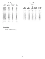
Страница 18: ...021 50 0128561 26 50 026 50 0128562 31 50 031 50 0128563 36 50 036 50 Accessories 0088154 Fluid Pressure Gauge Round Tip Orifice Size Part Tip 001 Volume 250 PSI Number Marking Inch oz Min G P M 0132...

Страница 19: ...19...

Страница 20: ...ies of the original manufacturers Wagner Spray Tech Corporation will provide the purchaser with reasonable information and assistance in making claims to the original manufacturers under their warrant...

Отзывы: