EN-USA_SECUSOL_TI-MA-111013-1121R800
31
3.7 Laying the Solar Circuit
Connecting the Solar Sub Assemblies
Please note: when the pipes of the solar circuit are
soldered, they must be flushed before connecting them
to the storage cylinder (see chapter 4, Start-Up).
●
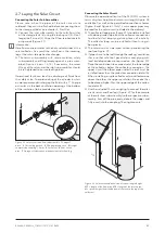
Connect the inlet subassembly to the solar flow inlet
of the storage tank (6) using the locking nut (5). Don‘t
forget the flat seal (2). Align the filling tap horizontally
or upwards (Figure 27).
Information:
Here flow and return refer to the hot and cold sides at the
solar collector. As a result the solar flow is the incoming
leg at the solar storage heat exchanger.
●
The return sub-assembly with solar circulation, safety
sub-assembly and filling/emptying cock is pre-assem-
bled. (Figure 26 pos. 13–15). If necessary, the screw
fittings of the return and the inlet subassemblies should
be re-tightened to ensure leak tightness.
Operational faults can lead to a discharge of fluids from
the safety valve. To avoid soaking of the cylinder insulati-
on we recommend discharging the fluid with a 1" Cu pipe
or similar via the back ventilation opening at the bottom
of the insulation (to be provided on site).
Figure 27 Solar circuit with flow sub-assembly
1
Copper-T-
piece;
2
Flat sealing gaskets;
3
Filling/emptying cock;
4
Straight
compression coupling, 12 mm;
5
Swivel nut;
6
Solar circuit
pipe;
7
Storage cylinder connection nozzle of solar flow leg.
L 10
L 11
H
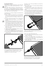
Figure 28 Solar circuit and definition of system length/height
L11
= length of the flow pipe;
L10
= length of the return pipe;
H
= system height (from the bottom of the tank to the top of the
collector).
Connecting the Solar Circuit
Observe the operational limits of the SECUSOL system in
terms of system height and solar circuit length (Figure 28
and table 1) as well as the permitted connection schemes
(Figure 5 and Figure 6). Only 12 mm copper pipes may
be used for the solar circuit (included in the delivery).
●
The collector loop pipes (figure 27) should be installed
with down-grade slope from the collector connections
to allow for fast emptying during times of inactivity.
The collector loop can be installed without using el-
bow pieces.
●
The solar circuit can be layed without penetrating the
roof see Figure 29.
●
If pipes have to be led through the roofing, ventilation
tiles or other safe roof penetrations complying with
local building codes are required on site (Figure 30).
Place the ventilation tile or pipe duct at the lower edge
of the collector, below the collector connection. The
upper rim of the elbow pipe under the roof must be
installed lower than the collector connection (detail A).
When installing a single collector or two collectors one
above the other, the upper ventilation tile or duct has
to be placed higher than the upper edge of the collec-
tor (detail B).
●
Use the included 12 mm coupling to connect the solar
circuit return and flow legs (Figure 27 for the example
of the solar flow sub-assembly) to the respective subas-
sembly. Saw off the pipe ends, deburr the ridges and
fully insert into the coupling. Then tighten nuts.
3
1
2
3
4
5
6
7

