20
5.
Set up tools
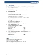
First, the correction values for all 8 tools have to be set to 0.00 in the tool memory in X and Z.
(Parameter
CAM
tool memory)
Tool 1 is the 0-tool,
The adjusted amounts are here generally maintained at X 0 and Z 0.
■
Run machine reference
■
Select tool
T1
to random diameter in
X
and run to beginning of workpiece in
Z
.
(if required, clamp turned part and turn splint)
Leave X-axis at turned diameter in
X
and set
Z
-axis
to beginning of workpiece.
Here, work piece zero point sets keyboard combination (Ctrl X) (Ctrl Z)
(Position display =
X
0.00
Z
0.00)
■
Select tool
T3
Move to same position in
X
and
Z
with tool
T3
where zero was set previously with
T1
(in
X
to turned diameter and in
Z
to workpiece starting point)
■
The new position value of
X
-axis is not
X 0.00 at the turned diameter, but e.g.
X 10.80
■
Enter in tool memory at
T3
:
New position value in
X
= 10.80
Radius is / 2
= 5.40
Adjusted amount in
X
= 5.40
■
The new position value of display
Z
-axis at start of work piece is e.g.
Z
– 8.00
Enter at
T3
in tool memory:
New position value in
Z
=
= - 8.00
Adjusted amount in
Z
= - 8.00
5.1
Set workpiece zero point
Select
T1
Drive with workpiece
T1
to turned diameter in
X
-axis.
(Position display in X-axis =
0.00
)
Measured turned diameter = e.g.
15.20
Now enter the required zero floating for
X
- axis in direct entry field.
G54 X- 15.20
(Enter)
New value in position display
= X 15.20
Содержание CC-D6200 hs
Страница 1: ...Operating Instructions CNC lathe With slant bed CC D6200 hs ...
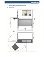
Страница 17: ...17 4 Specifications regarding the machine 4 4 Dimensions ...
Страница 25: ...25 8 Lubrication oft he machine ...
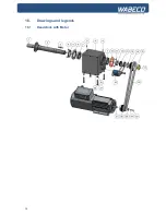
Страница 34: ...34 16 Drawings and legends 16 1 Headstock with Motor ...
Страница 36: ...36 16 Drawings and legends 16 2 Bed with lead screw ...
Страница 38: ...38 16 Drawings and legends 16 3 Cross slide with saddle apron ...
Страница 40: ...40 16 Drawings and legends 16 4 Tailstock ...
Страница 48: ...48 16 Drawings and legends 16 10 Operating console ...
Страница 52: ...52 17 Circuit diagram 17 1 Overall connection diagram see legend for circuit diagrams 17 3 ...
Страница 53: ...53 17 Circuit diagram 17 2 Axis motors and rotary encoders see legend for circuit diagrams 17 3 ...

