background image

36

Installation of the separate valves 

Installation of the separate valves 

Installation of the separate valves 

 Observe the following safety instructions for interventions in the braking system:


„

Observe the specifications of the vehicle manufacturer.


„

Deactivation when the supply pressure is too low: Switch the system off if 

the vehicle's supply pressure is too low.


„

Only intervene with the braking system if you have sufficient knowledge of 

the braking system and know and can take responsibility for the effect of 

your actions and all their consequences.


„

The braking system is under pressure. Before intervening with the braking 

system, make sure all reservoirs and lines are pressureless.


„

With braking intervention 

via separately installed valves

, the front axle 

must not be braked. Make sure that the vehicle's front axle can NOT be 

braked by the system. Braking intervention must only occur via the rear 

axle(s).

The following rules apply where separate valves together with the necessary pneumatic auxiliary components are 

installed for the autonomous braking function:


„

These auxiliary pneumatic components should be installed where possible close to the rear axle so that the line 

lengths to the braking system are kept short.


„

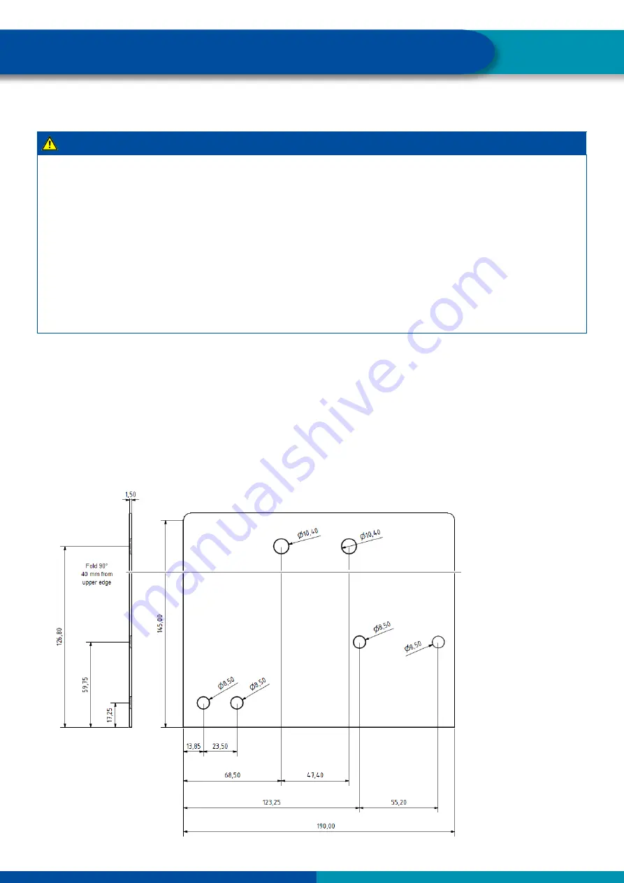
The components can be attached directly to the frame. It is more practicable, however, to mount the entire 

assembly on a steel angle bracket, which is then attached to the frame with just two bolts. Here is a drawing with 

the appropriate dimensions:


Содержание TAILGUARD

Страница 1: ...TAILGUARD FOR REFUSE COLLECTION VEHICLES...

Страница 2: ...2...

Страница 3: ...ehicles with an EBS braking system 18 5 3 Variant Autonomous braking via a prepared interface for TailGUARD 19 6 Installation of the ultrasonic sensors 20 6 1 The three standard applications 21 6 2 Po...

Страница 4: ...d to cope with both shorter and comparatively long distances in reverse gear for instance in cul de sacs where there is insufficient space for turning around In situations like this the driver has to...

Страница 5: ...e wrongly identified as being objects in the area behind the vehicle The sensors must also be installed with especially effective protection so that they are not damaged during the daily rigours of co...

Страница 6: ...accident regulations of the respective company as well as regional and national regulations Make provisions for a safe work environment Only trained and qualified technicians may carry out work on the...

Страница 7: ...hout a cable being connected Use electrically conductive bolted connections when fastening the ECUs to the vehicle frame Run the cable within metallic casings where possible e g inside the U beam or b...

Страница 8: ...lowing safety instructions for vehicles with braking intervention through TailGUARD Because the stopping distance becomes longer with heavily laden vehicles in particular when it is equipped with EBS...

Страница 9: ...ong do not wind them up but lay them in loops Observe the following safety instructions for handling ultrasonic sensors The surface to which the ultrasonic sensor is mounted must be even and must be a...

Страница 10: ...lso capable of detecting smaller objects behind the vehicle The most detailed description of TailGUARD for trailer vehicles can be found in the TEBS E system description You can download the latest ve...

Страница 11: ...ix ultrasonic sensors The maximum number of ultrasonic sensors that can be installed primarily depends on the respective lifting and tipping devices fitted to the refuse collection vehicle The sensor...

Страница 12: ...via additionally fitted pneumatic valves These valves are controlled by the Electronic Extension Module The amount of controlled braking pressure is also dependent upon the actual vehicle speed so th...

Страница 13: ...objects in the immediate vicinity of the rear of the vehicle and indicates the distances between them which is something that camera based systems are not capable of With a camera system the driver ha...

Страница 14: ...vehicle The vehicle manufacturer must not have prohibited use of this signal for external systems Expert approval If the vehicle is to be braked autonomously when approaching objects behind it and if...

Страница 15: ...g and warning If TailGUARD is only to be used for monitoring and warning purposes see Section 4 1 first variant the following components are required 2 to 6 ultrasonic sensors depending on your own re...

Страница 16: ...via which the ECU receives the vehicle speed signal This cable is routed either directly to the vehicle tachograph or to an interface provided by the vehicle manufacturer in accordance with ISO 16844...

Страница 17: ...e pressure reaches a pressure limiting valve 4 This makes it possible to set the maximum braking pressure that can be generated for an autonomous braking action In the case of refuse collection vehicl...

Страница 18: ...g On vehicles with a conventional braking system without an LSV regulator the output pressure is instead fed into the control input of the conventional relay valve via a two way valve 5 2 3 Separate v...

Страница 19: ...sing the existing EBS service brake system of the towing vehicle Depending on the interface to the towing vehicle the optical indications can be shown on the display on the vehicle s instrument panel...

Страница 20: ...sensors mechanically protected to avoid damage The ability to detect objects largely depends on the ultrasonic sensors positioning on the vehicle Make sure that the ultrasonic sensors are installed a...

Страница 21: ...nd to prevent them from being identified as objects behind the vehicle A third ultrasonic sensor with a straight housing 0 is positioned in the middle of the vehicle for better monitoring of this area...

Страница 22: ...ve media e g acids Route the cable to the connections so that no water can enter the connector Fasten the cable ties so that the cable is not damaged When using tools please note the instructions of t...

Страница 23: ...d on two horizontal planes A middle sensor in the lower level has been dispensed with here although an installation in an upright position would appear to be possible here In this case two sensors for...

Страница 24: ...ld be mounted wherever possible at a height of between 50 and 90 cm above the road surface The distance between the two outer sensors on the main level should be at least 1 50 metres In the case of sy...

Страница 25: ...rasonic sensors are connected directly to the ECU without the final cable routing The ECU is supplied with power via the power cable The diagnostic socket is connected to the ECU The multi core cable...

Страница 26: ...ounted with a retaining plate on the bin deflector which at the same time effectively protects the ultrasonic sensor against damage With this method the ultrasonic sensor is integrated into the retain...

Страница 27: ...ossibilities new fastening points have to be created for example as shown here by welding on round bars to which the cables can be fastened with cable ties The plug in couplings of the sensor cables s...

Страница 28: ...ing and tipping mechanism when it is fully raised for emptying the refuse collection vehicle Photo credit Petra Hoe FABION Markt Medien abfallbild de At such joints as for the rest of the cable routin...

Страница 29: ...nt sensor cable is routed to the Electronic Extension Module with the aid of cable ties The same applies for all the other cables These are usually routed from the exit point in the driver s cab along...

Страница 30: ...rake interface on the Daimler Econic Euro6 Plan your installation position so that cables cannot become kinked Fasten the cables and connectors so that the plug connections are not subjected to any te...

Страница 31: ...ension cables The documentation for the required cables and the product numbers can be found in the annex of the system description of the TailGUARD for Truck Bus as shown for example in the circuit d...

Страница 32: ...es Here is the documentation for the connections if TailGUARD should also autonomously brake the vehicle when objects are detected behind it with the aid of separately fitted valves see Section 5 2 Co...

Страница 33: ...at GIO 14 3 from Diagnosis V5 10 and the reversing signal has to be connected via terminal GIO14 pin 3 Further details can be found in Section 7 7 of the system description for TailGUARD for Truck Bu...

Страница 34: ...ed to the respective contacts in the electronics compartment However the installation will be considerably more flexible and clearer when using an interposed interface connector Here is an example for...

Страница 35: ...rst such series the Econic Euro 6 three plug housings with the following Mercedes Benz part numbers are required to connect the ECU A056 545 57 28 X1 A030 545 88 28 X2 and A007 545 46 26 X3 The displa...

Страница 36: ...servoirs and lines are pressureless With braking intervention via separately installed valves the front axle must not be braked Make sure that the vehicle s front axle can NOT be braked by the system...

Страница 37: ...nt towards the ground The prescribed nominal widths for the connections between the pneumatic components must be adhered to Some connecting line lengths should also not exceed stipulated maximum lengt...

Страница 38: ...hanism of the respective refuse collection vehicle as well as the measurements for the intended positions of the ultrasonic sensors WABCO prepares an individual set of parameters for TailGUARD that ca...

Страница 39: ...mounting positions for the ultrasonic sensors during installations so changes can be made The TailGUARD parameterisation must then be adapted accordingly in each case This is done by adjusting the par...

Страница 40: ...40 Notes...

Страница 41: ...41 Notes...

Страница 42: ...42 Notes...

Страница 43: ......

Страница 44: ...llion in 2016 Headquartered in Brussels Belgium WABCO has 13 000 employees in 40 countries For more information visit www wabco auto com WABCO NYSE WBC is a leading global supplier of technologies and...

Отзывы: