8
FUNCTIONAL DESCRIPTION
Your new air compressor can be used for operating paint, weed killer, and insecticide
sprayers, air tools, grease & caulking guns, sandblasters, inflation, etc. A tool with a higher air
demand than this compressor can produce may either not function, or not function well. It may
also cause the compressor to run without stopping for long periods of time, trying to maintain
pressure in the tank. This can cause either the motor or compressor pump to overheat and
damage them. Be sure the requirements of your tools can be met by the compressor.
To compress air, the piston in the pump moves up and down in the cylinder. On the down
stroke, air is drawn in through the inlet valve. Since the discharge valve remains closed, as the
piston goes up, the air in the cylinder is compressed. The inlet valve closes and compressed
air is forced out through the discharge valve, through the check valve and into the air receiver.
A check valve prevents it from going back into the pump. Working air is not immediately
available. Air becomes available for use when the receiver pressure is above that required by
the regulator at the air service connection. The pump continues to add air until the air receiver
pressure builds to the factory preset cut-out pressure of the pressure switch.
The air inlet filter openings must be kept clear of obstructions or else it could reduce air
delivery.
SET-UP
After removing it from the carton, and before you can use your compressor,
l
check for possible shipping damage to the unit and its components
WARNING
!
If you discover any damage, do not operate the compressor until it
is repaired. Failure to do so could result in possible serious injury.
l
check for missing parts and components
WARNING
!
If any parts are missing, do not operate the compressor until they
have been replaced. Failure to do so could result in possible serious injury.
l
add oil preparatory to using your compressor
l
retain packing materials until inspection is complete and the compressor runs
satisfactorily
You will need:
l
8 fl.oz. SAE-20 or SAE-10 non-detergent compressor oil
l
small flat screwdriver
AIR FILTER INSTALLATION
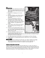
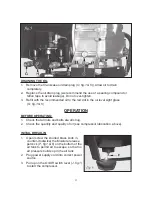
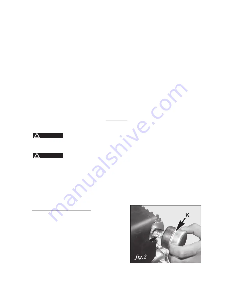
1. Loosely thread the Air inlet filter / muffler
(K, fig.1 & 2) into the hole in the side of the
cylinder head (
fig.2
).
2. To tighten it, use a 24 mm open-end or
combination wrench on the hexagonal
surfaces of the threaded end of the filter,
rather than using your hand on the light
metal housing, which can deform or break
off easily.
Содержание 650-4815
Страница 6: ...6 Nomenclature for No 650 4815 28 gal Air Compressor...
Страница 24: ...24 Nomenclatura para no Compresor de aire de 28 galones No 650 4815...
Страница 44: ...44 Nomenclature pour no 650 4815 Compresseur d air 28 gallons...
Страница 58: ...58 SCHEMATIC DRAWING ESQUEMA SCH MA 650 4815 v 090928...


