


23
Warranty card
1. Stamp of the company to carry out installation
VTS America Inc.
3535 Gravel Springs Rd Ext #203, Buford, GA 30519
PH: 470-809-6811, FAX: 470-809-6815
2. Factory number of device
3. Place of installation
4. Date of installation
5. Address, street
6. Apartment number
7. City
8. Postal code
Based on these Warranty Terms and Conditions, the company from the VTS Group (hereinafter: VTS) specified in the warranty card hereby guarantees to the owner
(hereinafter: Customer) that the Volcano VR, WING W100 - 200, WING E100
–
200, WING C100 - 200 devices (hereinafter: devices) sold by VTS will work without
malfunctions.
§ 1 Warranty period
1
.
The warranty period for the devices shall be 5 years following the date when the devices were purchased by the Customer.
2. The warranty period for the automation elements shall be 3 years following the date when the devices were purchased by the Customer.
43 The purchase date shall mean the date when VTS or a VTS distributor issued a VAT invoice documenting the sale of the device to the Customer.
§
2 Scope of warranty
1. If a complaint is recognized as justified, VTS shall, at its option, either replace the devices or their defective parts or repair them on the site of their installation or in
another place, after they are sent for repair.
2. If the warranty service is provided on the site of device installation in
the country of VTS’s registered office, VTS shall cover the costs of transporting VTS Licensed
Service Technicians and the costs of transporting spare parts. The current list of VTS Licensed Service Centres, hereinafter service centres, is available on
www.vtsgroup.com and in VTS business offices.
3. A warranty report is only processed if the device has been purch
ased in the country of VTS’s registered office.
4. A warranty service does not interrupt, suspend or change the warranty period; the warranty for replaced parts shall expire along with the expiry of the device warranty.
5. A warranty granted by VTS s
hall neither exclude nor limit or suspend the Customer’s rights arising from the regulations regarding implied warranty for d
efects of a sold
item.
6. These Warranty Terms and Conditions shall be binding for the parties of all contracts connected with the devices, unless the contract specifies otherwise, with the
consent of VTS.
§ 3 Exclusions
1. This warranty shall not include:
a. Any parts subject to normal wear and tear, consumables.
b. Any damage arising through no fault of VTS and device defects occurring for reasons other than inherent to the devices.
c. Device damage resulting from the impact of the surroundings, improper transport, storage.
d. Mechanical damage arising from incorrect operation and use of the device, repair and maintenance incompatible with the technical documentation enclosed with
the device, the Operation & Maintenance Manual or by individuals without proper qualifications.
e. Devices whose installation or start-up was conducted in a manner incompatible with the technical documentation enclosed with the device, the Operation &
Maintenance Manual or by individuals without proper qualifications.
f. Devices which were not inspected at least once a year and were not subject to current maintenance activities as required by the Operation & Maintenance Manual
or whose technical inspections or maintenance activities were conducted by individuals without proper qualifications.
g. Devices which were subject to modifications, changes of operation parameters, repair or replacement of parts without the written consent of VTS.
h. Any damage to or defects of devices which do not affect the functionality and correct operation of the devices.
2. This warranty shall not cover VTS’s o
bligation to ensure current maintenance, inspections or programming of devices.
3. This warranty shall cover neither VTS’s liability for an
y damage caused by device downtime while waiting for warranty services nor any damage to any property of the
Customer other than the devices.
4. In order to exercise their rights under the Warranty, the Customer shall file a complaint in the country where they have purchased the device. If a report is filed in
another country than the country of purchase, VTS is under no obligation to provide service under the warranty.
§ 4 Complaints
1. File any complaints online by sending the electronic application available on www.vtsgroup.com or on the phone by calling the complaint department along with
sending the electronic application specified above.
2. A complaint report ought to include:
- - device type and serial number,
- - date of device purchase and start-up,
- - device installation site,
- - business name of the seller and installer of the device,
- -
Customer’s phone number and the Customer's contact person,
- - description of the device malfunction (description of the incorrect functioning, specifying the damaged part).
3. If the Customer claims that the device was damaged during transport, complete device in the original packaging securing the device against damage shall be
delivered to the place of repair specified by VTS. The device serial number must be consistent with the number on the original packaging and in the Warranty Card.
4. Filing a complaint, the Customer shall deliver a copy of the VAT invoice documenting the purchase of the device covered by the complaint.
§ 5 Warranty service
1. Services arising from this warranty shall be provided within the 14 days following the report date. In special cases, this time limit may be extended to 30 days.
2. Any parts removed from the device by the service technicians within warranty services and replaced with new parts shall become the property of VTS.
3. Any costs arising from a groundless complaint report or interruptions in the work of
service technicians at the Customer’s request shall be borne by the Customer in
line with the technical service price list available on www.vtsgroup.com
4. VTS shall have the right to refuse to perform a warranty service if the Customer fails to pay for the device or for any previous technical service.
5. The Customer shall cooperate with the service technicians in terms of a warranty service performed on the site of the device installation, in particular by:
a. providing free access to the device in due time,
b. preparing the site for service provision, in particular providing any additional structures to access a device installed higher than 1.5 m above the floor and, if
necessary, to remove and re-install the devices,
c. disconnecting and connecting the hydraulic system (water, glycol system) and the freon system, performing additional works to allow the service technicians to handle
the complaint,
d. presenting the documents provided together with the device (a warranty card filled out by the installer),
e. making it possible for the service technicians to commence work immediately upon arrival, without unnecessary delay,
f f. providing, free of charge, all possible assistance in service provision (e.g. providing access to an electrical power source or lighting in the place of service provision),
g. taking the actions necessary to protect people and objects and following OHS regulations at the place where the warranty service is being performed, which includes
making sure that the service performance site meets the requirements defined in legal regulations.
6. The Customer shall promptly accept and confirm completion of the warranty service on the Service Card document. When in doubt as to the quality and completeness
of the warr
anty service, the Customer has the right to complain to VTS. Provisions of § 4 hereof shall apply to such a complaint as appr
opriate.
§ 6 Other provisions
1. In the event of any discrepancies between the Proposal plus the Purchase Order and these VTS Standard Warranty Terms and Conditions, VTS Standard Warranty
Terms and Conditions shall prevail. In such an event, any contradictory provisions of the Proposal and the Purchase Order shall not apply.
2. In the event of any discrepancies between a contract signed by the Parties and these VTS Standard Warranty Terms and Conditions, VTS Standard Warranty Terms
and Conditions shall prevail.
3. The Operation & Maintenance Manual is available on
www.vtsgroup.com.
Содержание WING C100-200
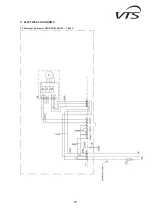
Страница 15: ...15 9 ELECTRICAL DIAGRAMS 9 1 Electrical diagram of WING W100 200 EC 1 240V ...
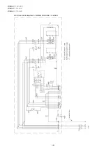
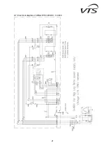
Страница 16: ...WING W100 200 WING E100 200 WING C100 200 16 9 2 Electrical diagram of WING C100 200 EC 1 240V ...
Страница 17: ...17 9 3 Electrical diagram of WING E100 EC 1 240V ...
Страница 18: ...WING W100 200 WING E100 200 WING C100 200 18 9 4 Electrical diagram of WING E100 EC 3 240V ...
Страница 19: ...19 9 5 Electrical diagram of WING E100 EC 3 480V ...
Страница 20: ...WING W100 200 WING E100 200 WING C100 200 20 9 6 Electrical diagram of WING E150 200 EC 3 240V ...
Страница 21: ...21 9 7 Electrical diagram of WING E150 200 EC 3 480V ...