WING
W100-200
WING
E100-200
WING
C100-200
8
VENTING OF DEVICE/DRAINING OF HEATING MEDIUM
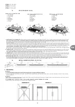
Venting of the curtain water coil followed by loosening the union connection on the outlet connection. In case of the vertical installation with the coils connection on the bottom side, the access
to the vent valve is by removing the side cover. To do it one should remove the screws (1) around the cover and lift the cover. There is a valve (2) with a hose.
VENT/DRAIN MARKING
2
3
3
2
1
IMPORTANT!
While venting the exchanger you should pay special attention to securing the device against accidental penetration of water into electrical elements.
IMPORTANT!
Remember to vent the heater, if it has been activated after a prior draining of the heating medium.
IMPORTANT!
Pay particular attention to the leak-tightness of connections, when filing the hydraulic system. Make sure that the water flowing from a leaky connection does not leak to the
electric engine (at the vertical instaallation).
CONNECTING OF POWER SUPPLY
IMPORTANT!
The system must be equipped with protective equipment that guarantees the disconnecting of the device on all poles of the power source.
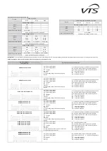
Connection to the electric system must be performed by a duly authorized and qualified person. Wire grommets are located on the back side of the curtain, a per drawing below.
•
Central gland [1]
o
Power supply input
•
Left gland [2]
o
Heating stage control signals input - only Wing air curtains with electric heat (E type)
•
Right gland [3]
o
Fan revolutions control signal input
CAUTION
For all connections (Power supply input, Heating stage control input, Fan revolutions
control signal input):
Minimum cables rating:
UL/CSA 600 Volts.
CABLES CROSSING BETWEEN THE GLANDS AND TERMINAL BLOCK
To ensure proper separation between high and low voltage cables, follow below wiring instruction:
Power supply cable (high voltage)
•
Cross the cables through the central gland (No. 1 on the drawing above).
•
Cross the cable through the central mounting point and tight the strain relief.
•
Gently pull the cable from outside to make it straight between the gland and mounting point. Then tighten the
gland.
•
Connect the wires to the relevant high-voltage terminals.
Heating stages control H
1
& H
2
(High voltage)
•
Cross the cables through the gland no. 2 on the drawing above.
•
Cross the cable through its mounting point (see diagram on the right) and tight the strain relief.
•
Gently pull the cable from outside to make it straight between the gland and mounting point. Then tight the
gland.
•
Connect the wires to the relevant high-voltage terminals.
Low voltage cable (0-10 volts fan revolutions control (low voltage)
•
Cross the cable between the small gland no 3 on the drawing above.
•
Mount the cable to the top mounting arm of the motor using cable tie (supplied with the curtain kit)
–
auxiliary
mounting point no 1.
•
Cross the cable through its mounting point (see diagram on the right) tighten the strain relief.
•
Cross the cable through auxiliary mounting points no 2 and 3.
•
Connect the wires to the relevant low-voltage terminals.
•
Gently pull the cable from outside to make it straight between the gland and mounting point. Then tighten the
gland.
*Heating stages high-voltage control signals concern only Wing air curtains with electric heat.
Cables marked as below:
Power supply cable
Electric heating stages control signal cable
0-10 volts fan revolutions control cable
EN
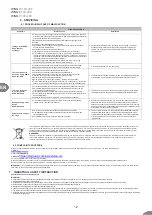
WORKING POSITION
A
horizontal (downward air feed)
drain
automatic venting
B
vertical (air feed from left to right)
drain
automatic venting
C
vertical (air feed from right to left
venting
drain
Heating stages cable
mounting point
Power supply cable
mounting point
0-10 volts cable
auxiliary mounting
point 2
0-10 volts cable
auxiliary mounting
point 1
Power supply cable
gland
Heating stages
cable gland
0-10 volts
cable gland
0-10 volts cable
auxiliary mounting
point 3
Содержание WING C100-200
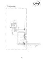
Страница 15: ...15 9 ELECTRICAL DIAGRAMS 9 1 Electrical diagram of WING W100 200 EC 1 240V ...
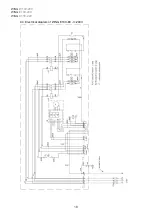
Страница 16: ...WING W100 200 WING E100 200 WING C100 200 16 9 2 Electrical diagram of WING C100 200 EC 1 240V ...
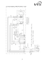
Страница 17: ...17 9 3 Electrical diagram of WING E100 EC 1 240V ...
Страница 18: ...WING W100 200 WING E100 200 WING C100 200 18 9 4 Electrical diagram of WING E100 EC 3 240V ...
Страница 19: ...19 9 5 Electrical diagram of WING E100 EC 3 480V ...
Страница 20: ...WING W100 200 WING E100 200 WING C100 200 20 9 6 Electrical diagram of WING E150 200 EC 3 240V ...
Страница 21: ...21 9 7 Electrical diagram of WING E150 200 EC 3 480V ...


