background image


13 


8.  TECHNICAL SPECIFICATION 

8.1.  WATER AIR CURTAIN 

 WING W100-200 

T

 temperature of water at the inlet to the device


T

 temperature of water at the outlet from the device 

T

p1 

 temperature of air at the inlet to the device


T

p2 

 temperature of air at the outlet from the device 

P

 heating output of the device


Q

 water flow


Δp –

 pressure drop in the heat exchanger


EN 


Parameters


WING W150


T

z

/T

[°F

]


164/158


176/140


158/122


140/104


T

p1 

[°F

]


41


50


59


68


41


50


59


68


41


50


59


68


41


50


59


68


III/1824[CFM]/61dB(A)*


P

g  

[MBH]


108


100


91


83


91


83


75


67


75


66


59


50


58


49


41


32


T

p2 

[°F

]


93


99


104


110


85


90


96


102


77


82


88


93


69


74


79


84


Q

[CFM]


0.82


0.76


0.70


0.64


0.70


0.64


0.59


0.53


0.59


0.53


0.47


0.41


0.41


0.35


0.29


0.23


Δp [psi

]


0.304


0.261  0.232  0.188  0.232  0.203  0.174  0.130  0.174  0.145  0.116  0.087  0.116  0.087  0.058  0.043 


II/1206[CFM]/48dB(A)*


P

g   

[MBH]


90


83


76


70


76


70


63


56


63


56


49


42


48


41


34


26


T

p2 

[°F

]


98


104


109


114


89


95


100


105


81


86


91


96


71


76


81


85


Q

[CFM]


0.70


0.64


0.59


0.53


0.59


0.53


0.47


0.41


0.47


0.41


0.35


0.29


0.35


0.29


0.23


0.17


Δp [psi

]


0.217


0.188  0.174  0.145  0.174  0.145  0.116  0.101  0.130  0.101  0.087  0.058  0.087  0.058  0.043  0.029 


I/835[CFM]/43dB(A)*


P

g  

[MBH]


73


68


62


57


62


57


51


46


51


45


40


34


39


33


27


16


T

p2 

[°F

]


104


110


115


120


95


100


105


110


85


90


95


99


75


79


83


83


Q

[CFM]


0.60


0.53


0.47


0.41


0.47


0.41


0.41


0.35


0.41


0.35


0.29


0.23


0.29


0.23


0.23


0.12


Δp [psi

]


0.159


0.130  0.116  0.101  0.116  0.101  0.087  0.072  0.087  0.072  0.058  0.043  0.058  0.043  0.029  0.014 


Parameters


WING W200


T

z

/T

[°F

]


164/158


176/140


158/122


140/104


T

p1 

[°F

]


41


50


59


68


41


50


59


68


41


50


59


68


41


50


59


68


III/2589[CFM]/62dB(A)*


P

g  

[MBH]


160


145


134


122


134


122


111


100


111


99


88


76


87


76


64


52


T

p2 

[°F

]


94


100


106


111


86


92


98


103


78


84


90


95


70


76


81


86


Q

[CFM]


1.17


1.12


1.00


0.94


1.00


0.94


0.82


0.76


0.82


0.76


0.64


0.59


0.64


0.59


0.47


0.41


Δp [psi

]


0.812


0.710  0.609  0.522  0.623  0.536  0.449  0.377  0.464  0.377  0.304  0.246  0.319  0.246  0.188  0.130 


II/1854[CFM]/48dB(A)*


P

g   

[MBH]


139


129


118


108


119


108


98


88


98


88


78


68


77


67


57


46


T

p2 

[°F

]


97


103


109


114


89


95


100


106


81


86


92


97


72


78


83


88


Q

[CFM]


1.06


1.00


0.88


0.82


0.88


0.82


0.76


0.64


0.76


0.64


0.59


0.53


0.59


0.53


0.41


0.35


Δp [psi

]


0.652


0.565  0.493  0.420  0.507  0.435  0.362  0.304  0.377  0.304  0.246  0.203  0.261  0.203  0.145  0.101 


I/1206[CFM]/45dB(A)*


P

g  

[MBH]


116


107


98


90


99


90


82


73


82


73


65


56


64


56


47


38


T

p2 

[°F

]


103


109


114


119


94


100


105


110


85


90


95


100


76


81


85


90


Q

[CFM]


0.88


0.82


0.76


0.70


0.76


0.70


0.64


0.59


0.64


0.59


0.47


0.41


0.47


0.41


0.35


0.29


Δp [psi

]


0.464


0.406  0.348  0.304  0.362  0.319  0.261  0.217  0.275  0.232  0.174  0.145  0.188  0.145  0.101  0.072 

Parameters


WING W100


T

z

/T

[°F

]


194/158


176/140


158/122


140/104


T

p1 

[°F

]


41


50


59


68


41


50


59


68


41


50


59


68


41


50


59


68


III/1088[CFM]/59dB(A)*


P

g  

[MBH]


60


55


50


46


50


45


40


35


39


34


29


23


27


17


14


12


T

p2 

[°F

]


89


95


101


107


81


87


92


98


73


78


83


88


63


64


71


78


Q

[CFM]


0.47


0.41


0.41


0.35


0.41


0.35


0.29


0.29


0.29


0.29


0.24


0.18


0.24


0.12


0.12


0.12


Δp [psi]


0.073


0.05

8


0.05

8


0.04

4


0.05

8


0.04

4


0.02

9


0.02

9


0.02

9


0.02

9


0.01

5


0.01

5


0.015


0.01

5


0.006


0.00

4


II/794[CFM]/48dB(A)*


P

g   

[MBH]


51


47


43


39


42


38


34


30


33


29


24


16


18


15


13


11


T

p2 

[°F

]


94


100


105


110


85


90


96


101


76


81


85


85


60


66


73


80


Q

[CFM]


0.41


0.35


0.35


0.29


0.35


0.29


0.24


0.53


0.24


0.24


0.18


0.12


0.12


0.12


0.12


0.06


Δp [psi

]


0.058


0.044  0.044  0.029  0.044  0.029  0.029  0.015  0.029  0.015  0.015  0.015  0.015  0.015  0.006  0.004 


I/518[CFM]/44dB(A)*


P

g  

[MBH]


40


37


33


30


33


30


27


23


26


22


15


13


15


13


11


9


T

p2 

[°F

]


101


106


111


116


91


96


100


104


79


83


83


89


64


70


76


83


Q

[CFM]


0.29


0.29


0.24


0.24


0.24


0.24


0.24


0.18


0.18


0.18


0.12


0.12


0.12


0.12


0.12


0.06


Δp [psi

]


0.029  0.029  0.029  0.015  0.029  0.015  0.015  0.015  0.015  0.015  0.015  0.000  0.015  0.006  0.004  0.003 


Содержание WING C100-200

Страница 1: ...Technical documentation Check us on WG US Rev 2 8 09 2020 WING W100 200 WING E100 200 WING C100 200 EN ...

Страница 2: ...ON OF DEVICE 5 3 2 1 HORIZONTAL INSTALLATION BY MEANS OF HOLDERS 6 3 2 2 VERTICAL ASSEMBLY USING INSTALATION HOLDERS 7 3 3 ASSEMBLY AND INSTALLATION GUIDELINES 7 4 ELEMENTS OF CONTTROLS 11 5 START UP OPERATION MAINTENANCE 11 5 1 START UP PUTTING INTO OPERATION 11 5 2 OPERATION AND MAINTENANCE 11 6 SERVICING 12 6 1 PROCEDURE IN CASE OF MALFUNCTION 12 6 2 COMPLAINT PROCEDURE 12 7 INDUSTRIAL SAFETY I...

Страница 3: ...heck connections for tightness and vent the system Perform the electrical connection Make sure the device is correctly connected according to the diagram In the case of an electrical curtain vacuum the heaters to avoid the unpleasant smell of burning dust Turn the power on and start the device 2 STRUCTURE INTENDED USE PRINCIPLE OF OPERATION 2 1 INTENDED USE For the convenience of users as well as ...

Страница 4: ...s a valve actuator for WING W100 200 WING air curtains can be additionally equipped with a wall mounted DX controller The DX controller has a three position heating switch In the case of a water curtain to guarantee the proper functioning of the water valve the heating switch must be set to position II central otherwise the valve will not open The system of WING E100 200 is equipped with a safety ...

Страница 5: ...t have a positive effect on curtain operation doors or windows that are constantly open in the room thus creating a draft presence of awning roofs etc on the outer side of the door constant and open access to staircases available through the room the chimney draft effect use of revolving doors 3 1 ASSEMBLY DISASSEMBLY OF JUNCTION BOX COVER To access the terminal block remove the screws from the ju...

Страница 6: ...ers 3 Tighten the screws 2 and close the handle scovers 4 W1 in W2 in WING W E C100 30 WING W E C150 20 30 WING W E C200 36 35 OPTION II Installation brackets with their arms faced downwards Installation consists in screwing brackets to the curtain 1 Tomount the brackets to the curtain with the housing upside down punch holes 5 from the outside in the shields 4 using a hammer and a screw Click the...

Страница 7: ...r and aluminum structural elements in the heat exchanger and electric heaters IMPORTANT The WING EH air curtains are not intended for the installation on suspended ceilings 3 3 INSTALLATION GUIDELINES CONNECTION OF THE HEATING MEDIUM When connecting the air curtain to the heating water pipeline secure the coil headers from excessive torque using set of two keys The weight of installed pipelines sh...

Страница 8: ...n Power supply cable high voltage Cross the cables through the central gland No 1 on the drawing above Cross the cable through the central mounting point and tight the strain relief Gently pull the cable from outside to make it straight between the gland and mounting point Then tighten the gland Connect the wires to the relevant high voltage terminals Heating stages control H1 H2 High voltage Cros...

Страница 9: ...plying 240VAC 3 second heating stage controlled by applying 240VAC Ai 0 10VDC analog input for fan speed regulation G Reference ground for 0 10VDC speed regulation connected internally 1L1 connected internally 2L2 connected internally WING E150 240 3 60 EC WING E200 240 3 60 EC L1 Power supply phase L2 Power supply phase L3 Power supply phase Ground 1L1 N C L2 N C 2 first heating stage controlled ...

Страница 10: ...ON when the motor is running at least 45 of its full capacity Starting electric heating coils when the motor is switched OFF can be dangerous and can lead to damage to the device Electric heating coils are divided into two independent sections controlled by applying 240VAC to terminals 2 and 3 on the terminals of electric curtains EN IMPORTANT It is recommended to connect wires to the terminal str...

Страница 11: ...onduits the supply conduits in particular It is advised to use vent valves in the highest point of the system It is recommended to install shut off valves directly after the device should the disassembly of the device be necessary All protectiveequipment isto beinstalledbefore the pressure increases according tomaximum the permissiblepressure ratingof 232 psi Hydraulic connection should be free of...

Страница 12: ... of internal breaking of the collecting pipes Relation between the leaking and a potential mechanical damage to the exchanger Leaking of vent valve elements or drain plug Parameters of the heating medium pressure and temperature should not exceed the permissible values Correctness of the draining of the exchanger type of agent it cannot be any aggressive substance Al or Cu active Circumstances in ...

Страница 13: ... 1 00 0 94 1 00 0 94 0 82 0 76 0 82 0 76 0 64 0 59 0 64 0 59 0 47 0 41 Δp psi 0 812 0 710 0 609 0 522 0 623 0 536 0 449 0 377 0 464 0 377 0 304 0 246 0 319 0 246 0 188 0 130 II 1854 CFM 48dB A Pg MBH 139 129 118 108 119 108 98 88 98 88 78 68 77 67 57 46 Tp2 F 97 103 109 114 89 95 100 106 81 86 92 97 72 78 83 88 Qw CFM 1 06 1 00 0 88 0 82 0 88 0 82 0 76 0 64 0 76 0 64 0 59 0 53 0 59 0 53 0 41 0 35 ...

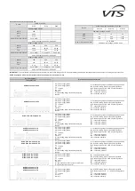
Страница 14: ...200 COLD AIRCURTAIN Parameters WING C100 WING C150 WING C200 Fan speed III II I III II I III II I Qp CFM 1147 882 618 1883 1324 882 2707 2001 1377 noise level dB A 62 49 45 63 49 43 63 49 45 The noise level has been measured within a 10 ft distance from the device reference conditions semi open space wall mounted device Parameters WING W100 200 WING E100 200 WING C100 200 unit of measure W100 W150...

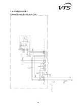
Страница 15: ...15 9 ELECTRICAL DIAGRAMS 9 1 Electrical diagram of WING W100 200 EC 1 240V ...

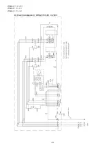
Страница 16: ...WING W100 200 WING E100 200 WING C100 200 16 9 2 Electrical diagram of WING C100 200 EC 1 240V ...

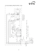
Страница 17: ...17 9 3 Electrical diagram of WING E100 EC 1 240V ...

Страница 18: ...WING W100 200 WING E100 200 WING C100 200 18 9 4 Electrical diagram of WING E100 EC 3 240V ...

Страница 19: ...19 9 5 Electrical diagram of WING E100 EC 3 480V ...

Страница 20: ...WING W100 200 WING E100 200 WING C100 200 20 9 6 Electrical diagram of WING E150 200 EC 3 240V ...

Страница 21: ...21 9 7 Electrical diagram of WING E150 200 EC 3 480V ...

Страница 22: ...fication The company that installed the equipment Date of notification Type of device Factory number Date of purchase Date of installation Place of installation Detailed description of defect Contact person Name and surname Telephone E mail This field must be filled if the complaint notification refers to the following equipment VOLCANO VR1 VR2 VR3 and VRMini unit and WING air curtains ...

Страница 23: ...their rights under the Warranty the Customer shall file a complaint in the country where they have purchased the device If a report is filed in another country than the country of purchase VTS is under no obligation to provide service under the warranty 4 Complaints 1 File any complaints online by sending the electronic application available on www vtsgroup com or on the phone by calling the compl...

Отзывы: