13
General information
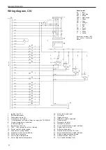
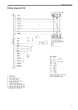
Wiring diagram DCU
Cable colors
BL =
Blue
LBL
=
Light blue
BN =
Brown
LBN
=
Light brown
GN =
Green
GR =
Gray
OR =
Orange
P
=
Pink
R
=
Red
SB =
Black
VO =
Violet
W =
White
Y
=
Yellow
Cable cross section = 0.75 mm
2
unless otherwise stated.
1.
Stop switch
2.
Start switch
3.
1-pin connector block
4.
Horn, buzzer alarm
5.
Easy Link connector block
6.
RPM-potentiometer
7.
Indicator engine operation
8.
8-pin connector engine interface
9.
8-pin connector engine interface
10. Termination resistance 120 Ohm
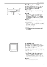
11. Display Control Unit (DCU)
Содержание TAD734GE
Страница 1: ...EMS 2 Industrial engines TAD734GE Installation 1 1 I ...
Страница 2: ......
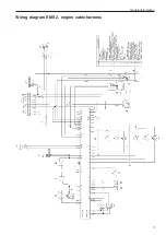
Страница 13: ...General information 11 Wiring diagram EMS 2 engine cable harness ...
Страница 45: ...43 References to Service bulletins Group No Date Concerning ...
Страница 46: ... Notes ...
Страница 48: ...7747352 English 10 2009 ...


