General information
12
16.
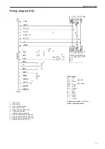
Alarm, low coolant level
17.
Fuel alarm
18.
Diagnostic lamp
19.
Indicator, engine overspeed
20.
Running lamp
21.
Pre-heater indicator
22.
Pre-heating contact
23.
8-pin connector block, engine interface
24.
Primary control switch
25.
Battery voltage alarm
26.
Termination resistance 120 Ohm
27.
8-pin connector block, engine interface
28.
Switch, engine protection disable
29.
Connector block, Easy Link
30.
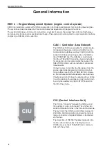
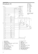
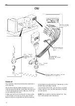
CIU (Control Interface Unit)
Wiring diagram, CIU
Cable colors
BL
= Blue
LBL = Light blue
BN
= Brown
LBN = Light brown
GN = Green
GR = Gray
OR = Orange
P
= Pink
R
= Red
SB
= Black
VO
= Violet
W
= White
Y
= Yellow
Wire cross-section = 0.75
mm
2
unless otherwise
stated.
1.
Ignition lock (15+)
2.
RPM-potentiometer
3.
Tachometer (code 14)
4.
Oil pressure, instrument
5.
Oil temperature, instrument
(Does not apply for TAD734GE)
6.
Coolant temperature, instrument
7.
Instrument lighting
8.
Idle contact, two-way
9.
1500 / 1800 rpm guard contact, two-way
10.
Starter contact, spring loaded
11.
Stop contact, spring loaded
12.
Diagnostic switch, spring loaded
13.
Alarm, low oil pressure
14.
Alarm, high oil temperature
15.
Alarm, high coolant temperature
Содержание TAD734GE
Страница 1: ...EMS 2 Industrial engines TAD734GE Installation 1 1 I ...
Страница 2: ......
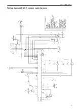
Страница 13: ...General information 11 Wiring diagram EMS 2 engine cable harness ...
Страница 45: ...43 References to Service bulletins Group No Date Concerning ...
Страница 46: ... Notes ...
Страница 48: ...7747352 English 10 2009 ...


