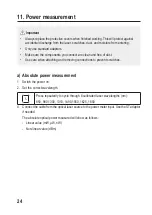
b) Relative power (loss) measurement
Use this function to calculate the estimated loss of all connectors and cable in a link.
An additional optical laser source is needed.
1. Connect a standard test cable from the optical laser source to the power meter input. Use
the ST adaptor if needed.
2. Set the correct wavelength.
Press repeatedly to cycle through 8 calibrated laser wavelengths (nm):
850, 980,1300, 1310, 1490,1550, 1625, 1650
3. The screen will display the absolute optical power measured:
- Linear value (mW, μW, nW)
- Non-linear value (dBm)
4. Press the dB button to save the absolute optical power measured.
- It will be stored as a reference value and shown as “xx.xx dBm” on the second line of
the display.
- The unit on the main display will switch to “dB” and should show “00.00”.
5. Now remove the connected optical fibre cable from the measuring input and connect the
second cable that you want to compare to the first one.
- The difference between the current optical power value and the reference power value
will be calculated.
- The difference will be shown as “xx.xx dB” on the third line of the display.
- This is the approximate insertion loss of the jumper cable.
12. Frequency identification function
• When connected to a laser source, the meter will automatically detect the following frequen-
cies: 270 Hz, 1000 Hz, 2000 Hz.
• The detected frequency will show on the display.
25
Содержание 2299816
Страница 55: ......


