background image


SmartCrystal™ Diamond 

n ° : MUV140036 

Version : A12 

USER MANUAL 

Date : 11/01/2018 


www.volfoni.com


This document is the property of the Co VOLFONI and may not be reproduced or disclosed without permission. 


89


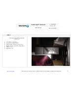
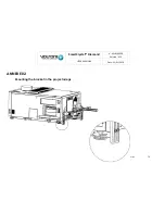
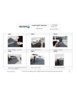
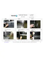
ANNEXE 05 


Wall mounting solution 


Содержание SmartCrystal Diamond

Страница 1: ...nd n MUV140036 Version A12 USER MANUAL Date 11 01 2018 www volfoni com This document is the property of the Co VOLFONI and may not be reproduced or disclosed without permission 1 model VPSP 08000 VPSP...

Страница 2: ...et 6 d Volfoni passiveglasses 6 e I GENERAL PRESENTATION 7 1 SmartCrystal Diamond SCD presentation 7 The SmartCrystal Diamond Box 8 a SmartCrystal Diamond Controller 10 b 2 Requirements andimportant r...

Страница 3: ...e SmartCrystal Diamond box on the bracket and positioning in front of the projector 31 3 The SmartCrystal Diamond box tilt adjustment and locking 34 4 2 D 3 D position stops positioning 37 5 Electrica...

Страница 4: ...xx SCD bracket installation 65 ANNEXE 02 79 Mounting the bracket in the projectorlegs 79 ANNEXE 03 83 Mounting the bracket in the projectorbench 83 ANNEXE 04 87 Mounting the desktopbracket 87 ANNEXE 0...

Страница 5: ...istie Barco NEC For every other model we invite you to contact Volfoni directly Contents of this manual b This manual is aimed at providing the SmartCrystal Diamond installation instructions and maint...

Страница 6: ...n of the bracket d The SmartCrystal Diamond is assembled on a specific bracket This manual is based on the assumption that all the specifications for the installation of the bracket have been respecte...

Страница 7: ...lasses 2 pairs Optional anti reflection filter for room window USB key with aligning pattern and technical data Tools holding screws Cleaning wipe Quick Start 1 USB Key Wipes x2 2 RJ45 Cable Used for...

Страница 8: ...SmartCrystal Diamond technology splits up the incident light flux into three separate fluxes The central flux full image The upper flux upper half image The lower flux lower half image If you want to...

Страница 9: ...two wheels to adjust the system see below On both sides left and right of the SmartCrystal Diamond Box are fitting wheels for the upper and lower half images They enable you to adjust the position of...

Страница 10: ...er center 3 Sync_3D BNC connector Synchronization signal generated by the projector or another source 4 SCD Box interface SUBD9 connector This interface is used to run the SCD Box 5 Bracket connector...

Страница 11: ...l the SmartCrystal Diamond IT IS ABSOLUTELY ESSENTIAL TO MEET THE FOLLOWING CRITERIA TO INSTALL THE SMARTCRYSTAL DIAMOND BOX Room configuration a Minimum size of the room window 40cm X 40 cm Such an o...

Страница 12: ...ection room window must not depolarize light The image size at 2cm from the lens must not exceed 10 cm X 7 cm This size corresponds to the size of the SmartCrystal Diamond Box inflow window Film theat...

Страница 13: ...which enables you to fit its position opposite the projector with high precision Height angle distance from the projector i e projector lens and lateral movement for the 2D 3D modes WARNING To avoid...

Страница 14: ...ut permission 14 The technical Specifications b DIMENSIONS 900 x 310 x 150mm NET WEIGHT 13 kg PACKING DIMENSIONS 1000 x 370 x 250mm GROSS WEIGHT 14 kg FINISH IN Aluminum powder coating COLOR Aluminum...

Страница 15: ...disclosed without permission 15 List of accessories c The kit includes all necessary accessories for mounting the support in all possible ways It also includes the necessary screws The bracket is inc...

Страница 16: ...he bracket overview d Installation and adjustment on the support overview Several steps to install the SCD on the Bracket Fixing the SCD on the support with 4 screws Adjustment of the Horizontal posit...

Страница 17: ...property of the Co VOLFONI and may not be reproduced or disclosed without permission 17 Setting 2D and 3D position The bracket has two sensors to define 2D and 3D position The position of theses sens...

Страница 18: ...This document is the property of the Co VOLFONI and may not be reproduced or disclosed without permission 18 Appendix e Status LED status settings electrical wiring 01 Power Outlet 02 Link Control 03...

Страница 19: ...The bracket installation When installing the bracket it is important to keep in mind the goal is the following The upper plate of the bracket must be pre positioned 13cm far from the beam center so as...

Страница 20: ...ion A12 USER MANUAL Date 11 01 2018 www volfoni com This document is the property of the Co VOLFONI and may not be reproduced or disclosed without permission 20 The bracket s elements and the differen...

Страница 21: ...nting the bracket in the projector bench You will find others way to install the bracket below Please have a look before starting the installation ANNEXE 02 Mounting the bracket in the projector legs...

Страница 22: ...MANUAL Date 11 01 2018 www volfoni com This document is the property of the Co VOLFONI and may not be reproduced or disclosed without permission 22 STEP 03 STEP 04 Fix F parts using 8 units of M and N...

Страница 23: ...STEP 05 If the length of the projector s lens is more than 15 centimeters Please follow the procedure if not please go directly to the STEP 08 STEP 06 STEP 07 Positioning connecting bars on each side...

Страница 24: ...erty of the Co VOLFONI and may not be reproduced or disclosed without permission 24 STEP 10 STEP 11 Use H part Slide the H part on the end of J parts STEP 12 STEP 13 Put the H part with the L screws i...

Страница 25: ...oni com This document is the property of the Co VOLFONI and may not be reproduced or disclosed without permission 25 STEP 16 STEP 17 Put the K parts in the middle of the H part Use the G part STEP 18...

Страница 26: ...ment is the property of the Co VOLFONI and may not be reproduced or disclosed without permission 26 STEP 20 STEP 21 Adjust the height of the G part Add the I pieces at the end of H part STEP 22 STEP 2...

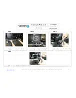
Страница 27: ...rmission 27 STEP 24 STEP 25 Unscrew 2 bracket position sensors In this configuration move right position sensor from its position till a position that will allow to put bracket upper plate face to pro...

Страница 28: ...Co VOLFONI and may not be reproduced or disclosed without permission 28 STEP 28 STEP 29 Power on bracket and check 2 leds red Bracket upper plate is at 2D position STEP 30 STEP 31 Use first contact Br...

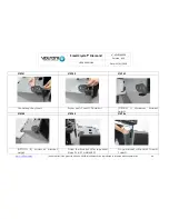
Страница 29: ...may not be reproduced or disclosed without permission 29 STEP 32 STEP 33 Unscrew and move the sensor limit to place the bracket upper plate Position the sensor limit to have the bracket upper plate p...

Страница 30: ...osed without permission 30 STEP 36 STEP 37 Set bracket upper plate at middle position Set bracket tilt at 0 Check distance between bracket upper plate and middle of projector lens Right distance shoul...

Страница 31: ...atter during the assembly of the SmartCrystal Diamond Box on the carriage Assemble the SmartCrystal Diamond with the bracket carriage After positioning the SmartCrystal Diamond Box fix it on the carri...

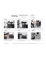
Страница 32: ...sclosed without permission 32 STEP 42 STEP 43 Move bracket in order SCD entrance windows will be at approximately 2cm from projector lens Check and adjust bracket position same distance for both side...

Страница 33: ...operty of the Co VOLFONI and may not be reproduced or disclosed without permission 33 STEP 46 STEP 47 Use first contact SCD will reach automatically 2D position Use a white pattern Move slightly 3D br...

Страница 34: ...operly towards the light coming from the projector Make the carriage slide so that the beam of light from the projector lights up the side of the SmartCrystal Diamond Box See Fig 19which shows a view...

Страница 35: ...Box as mentioned by the figures below This step might alter slightly the position of the SCD Box in relation to the projector lens Check again removal bringing close by making the carriage slide There...

Страница 36: ...document is the property of the Co VOLFONI and may not be reproduced or disclosed without permission 36 There are more information in looking at ANNEXE 06 Precision and tilt adjustments STEP 50 STEP 5...

Страница 37: ...een side and make sure that the central image is properly centered At this moment do not worry about the position of the upper and lower halfimages Look at the SmartCrystal Diamond Box inflow window a...

Страница 38: ...he Co VOLFONI and may not be reproduced or disclosed without permission 38 STEP 52 STEP 53 Check inflow image is well centered vertically and horizontally Image size has to be 10cm x 7cm Check 3 outfl...

Страница 39: ...www volfoni com This document is the property of the Co VOLFONI and may not be reproduced or disclosed without permission 39 STEP 56 STEP 57 Put wires properly Connect all cables except synchronizati...

Страница 40: ...and the SCD Controller Connect the synchronization cable GPIO37 BNC or GPIO15 BNC with the projector and the SCD Controller Connect the SUBD15 cable with the SCD Box and the bracket Connect the brack...

Страница 41: ...closed without permission 41 STEP 58 STEP 59 Use the 1st contact to position the SCD in 2D position Look at the Controller box screen If 2D 00Hz Bracket OK nothing more to do If 2D 00Hz Bracket unread...

Страница 42: ...BOX OPTICAL BOX DARKTIME VSSP 10200 VSSP 13300 350 S VSSP 10100 VSSP 13200 1000 S VSSP 10000 VSSP 13200 1000 S If you notice an excessive ghosting effect test other values for the Darktime increasing...

Страница 43: ...of the SmartCrystal Diamond Box On one side of the SmartCrystal Diamond Box you will find the up down adjustment wheels of the upper half image at the top so as of the lower half image at the bottom T...

Страница 44: ...he image Fitting the upper half image The purpose of this step is to superimpose all the information of the upper half of the image proceeding as following First of all you need to make sure that the...

Страница 45: ...e the vertical lines at the center of the upper image using the left right wheel located at the top of the device n 1 wheel of the figure 5 When the aligning is correct at the center the vertical line...

Страница 46: ...image using the up down wheel located at the top of the device n 3 wheel of the figure 5 Focus mainly on the center of the image the horizontal lines at the top of the image are probably still irregu...

Страница 47: ...a satisfying result The adjustment is satisfying when there is no image splitting on the upper half image anymore Now as the adjustment of the top image is completed you have to lock it To do so you...

Страница 48: ...f the vertical alignment moved remove the locking mechanical piece redo the vertical alignment and fix again the locking mechanical piece until having a perfect vertical alignment after tightening the...

Страница 49: ...alignment moved remove the locking mechanical piece redo the alignment and fix again the locking mechanical piece until having a perfect alignment after tightening the knurl screw It might be necessa...

Страница 50: ...step is to superimpose all the information of the lower half of the image proceeding as following First of all you need to make sure that the adjustable wheel is unlocked To do so you have to maintain...

Страница 51: ...s Align superimpose the vertical lines at the center of the lower image using the left right wheel located at the bottom of the device n 2 wheel of the image 5 As the aligning is correct at the center...

Страница 52: ...lower image using the up down wheel located at the bottom of the device n 4 wheel of the figure 5 Focus mainly on the center of the image the horizontal lines at the top of the image are likely still...

Страница 53: ...tment is satisfying when there is no splitting information on the lower half image Final locking Now as the adjustment of the bottom image is completed you have to lock it To do so you have to maintai...

Страница 54: ...If the vertical alignment moved remove the locking mechanical piece redo the vertical alignment and fix again the locking mechanical piece until having a perfect vertical alignment after tightening th...

Страница 55: ...ent moved remove the locking mechanical piece redo the alignment and fix again the locking mechanical piece until having a perfect alignment after tightening the knurl screw It might be necessary to r...

Страница 56: ...com This document is the property of the Co VOLFONI and may not be reproduced or disclosed without permission 56 The result expected STEP 70 With the Volfoni test pattern you will a perfect match bet...

Страница 57: ...isclosed without permission 57 If you use the Cross Hatch test pattern line 1 pixels you may observe some local disparities The figure below shows the maximum disparity in overlay of the two images We...

Страница 58: ...e in order to deflect the reflection or to change it 2 Filter assembly It is absolutely essential to carry out this process after the SmartCrystal Diamond Box has been dismantled from the bracket and...

Страница 59: ...ion of the SCD system Change of the default working settings 3 D mode automatic detection for instance Diagnosis unavailable 2 SCD software version The system is run by the SCD Controller By default t...

Страница 60: ...tem is up to date If the version is not the latest accept and launch the new version loading During this process warning Do not disconnect the SCD Controller from your computer Do not unplug the SCD C...

Страница 61: ...D Box aligning again using the pattern No 3 D effect Problem on the silvered screen Projector settings are not right The SCD Box is not connected with the SCD Controller The SCD Controller is not plug...

Страница 62: ...e switch from TRUE to INVERTED or conversely on the projector Flickering image The SmartCrystal Diamond settings are faulty The content is not 3 D The image frequency given by the projector is not rig...

Страница 63: ...artCrystal Diamond where the skin is exposed to liquid crystal material we recommend that you immediately wash the area with soap and water In case of eye exposure to liquid crystal material please se...

Страница 64: ...and regulations your product should be disposed of separately from household waste When this product reaches the end of its life take it to a collection point designated by local authorities Some coll...

Страница 65: ...NEXE 01 VASP 09xxx SCD bracket installation The technical Specifications DIMENSIONS 900 x 310 x 150mm NET WEIGHT 13 kg PACKING DIMENSIONS 1000 x 370 x 250mm GROSS WEIGHT 14 kg FINISH IN Aluminum powde...

Страница 66: ...ed or disclosed without permission 66 List of accessories The kit includes all necessary accessories for mounting the support in all possible ways It also includes the necessary screws The bracket is...

Страница 67: ...7 Installation and adjustment on the support overview Several steps to install the SCD on the Bracket Fixing the SCD on the support with 4 screws Adjustment of the Horizontal position SCD must be as c...

Страница 68: ...property of the Co VOLFONI and may not be reproduced or disclosed without permission 68 Setting 2D and 3D position The bracket has two sensors to define 2D and 3D position The position of theses sens...

Страница 69: ...i com This document is the property of the Co VOLFONI and may not be reproduced or disclosed without permission 69 The bracket installation STEP 01 STEP 02 Choose your configuration ANNEXE 01 to 05 Br...

Страница 70: ...AL Date 11 01 2018 www volfoni com This document is the property of the Co VOLFONI and may not be reproduced or disclosed without permission 70 STEP 03 STEP 04 Fix D E parts Fix O part STEP 05 Part 1...

Страница 71: ...t permission 71 STEP 06 STEP 07 If the length of the projector s lens is more than 15 centimeters Please follow the procedure if not please go directly to the STEP 10 Do not forget to screw 2 L parts...

Страница 72: ...www volfoni com This document is the property of the Co VOLFONI and may not be reproduced or disclosed without permission 72 STEP 10 STEP 11 Bracket feet installation Parts tools Fix screws bolts on P...

Страница 73: ...2 USER MANUAL Date 11 01 2018 www volfoni com This document is the property of the Co VOLFONI and may not be reproduced or disclosed without permission 73 STEP 14 STEP 15 Put the bolt in the middle ho...

Страница 74: ...ay not be reproduced or disclosed without permission 74 STEP 16 STEP 17 Remove protection guide Remove 2 bracket position sensors wires from guide STEP 18 STEP 19 Unscrew 2 bracket position sensors In...

Страница 75: ...m This document is the property of the Co VOLFONI and may not be reproduced or disclosed without permission 75 STEP 20 General view of the bracket electronic 1st button not used 2nd button reset butto...

Страница 76: ...he Co VOLFONI and may not be reproduced or disclosed without permission 76 STEP 21 STEP 22 Power on bracket Check 2 leds red Bracket upper plate is at 2D position STEP 23 STEP 24 Use left contact Brac...

Страница 77: ...e reproduced or disclosed without permission 77 STEP 25 STEP 26 Unscrew 2 screws of the rings on both side of the trolley Loosen stud bolt of the trolley STEP 27 STEP 28 Set bracket upper plate at mid...

Страница 78: ...reproduced or disclosed without permission 78 STEP 29 STEP 30 In case of bracket upper plate too high or too low Readjust its position by modifying D E parts position Check horizontality is good STEP...

Страница 79: ...V140036 Version A12 USER MANUAL Date 11 01 2018 www volfoni com This document is the property of the Co VOLFONI and may not be reproduced or disclosed without permission 79 ANNEXE 02 Mounting the brac...

Страница 80: ...is the property of the Co VOLFONI and may not be reproduced or disclosed without permission 80 STEP 01 STEP 02 STEP 03 Assemble parts A L and M Screw parts A and L Repeat operation STEP 04 STEP 05 ST...

Страница 81: ...t be reproduced or disclosed without permission 81 STEP 07 STEP 08 STEP 09 Screw parts D and L Unscrew projector foot Repeat process with part E Insert parts F and G in each projector foot STEP 10 STE...

Страница 82: ...the property of the Co VOLFONI and may not be reproduced or disclosed without permission 82 STEP 13 STEP 14 STEP 15 Adjust according to the lens installed Adjust manually with the Tighten screws from...

Страница 83: ...140036 Version A12 USER MANUAL Date 11 01 2018 www volfoni com This document is the property of the Co VOLFONI and may not be reproduced or disclosed without permission 83 ANNEXE 03 Mounting the brack...

Страница 84: ...OLFONI and may not be reproduced or disclosed without permission 84 STEP 01 STEP 02 STEP 03 Use adequate screws Screw parts F and G Pedestal OPTION 1 Maximum bracket height STEP 04 STEP 05 STEP 06 OPT...

Страница 85: ...ocument is the property of the Co VOLFONI and may not be reproduced or disclosed without permission 85 STEP 07 STEP 08 STEP 09 Once fitted in place Insert K parts covers If needed lenght can be increa...

Страница 86: ...12 USER MANUAL Date 11 01 2018 www volfoni com This document is the property of the Co VOLFONI and may not be reproduced or disclosed without permission 86 STEP 13 STEP 14 OPTION 1 Bracket at maximum...

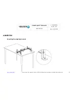
Страница 87: ...nd n MUV140036 Version A12 USER MANUAL Date 11 01 2018 www volfoni com This document is the property of the Co VOLFONI and may not be reproduced or disclosed without permission 87 ANNEXE 04 Mounting t...

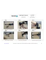
Страница 88: ...document is the property of the Co VOLFONI and may not be reproduced or disclosed without permission 88 STEP 01 STEP 02 STEP 03 Take parts A H M and N Screw parts A and H Adjust height STEP 04 STEP 0...

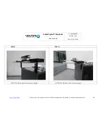
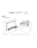
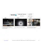
Страница 89: ...amond n MUV140036 Version A12 USER MANUAL Date 11 01 2018 www volfoni com This document is the property of the Co VOLFONI and may not be reproduced or disclosed without permission 89 ANNEXE 05 Wall mo...

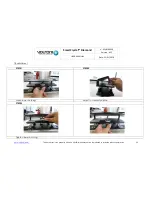
Страница 90: ...erty of the Co VOLFONI and may not be reproduced or disclosed without permission 90 ANNEXE 06 Precision and tilt adjustments Height precision adjustment STEP 01 STEP 02 STEP 03 Loosen marked screws Lo...

Страница 91: ...UAL Date 11 01 2018 www volfoni com This document is the property of the Co VOLFONI and may not be reproduced or disclosed without permission 91 Tilt adjustment STEP 01 STEP 02 Losen lower bushing Adj...

Страница 92: ...he models VASP 09XXX please see annexe 08 WARNING Please remove SCD product and disconnect the power supply cable before to disengage the bracket STEP 01 STEP 02 STEP 03 If you have a motor problem an...

Страница 93: ...e property of the Co VOLFONI and may not be reproduced or disclosed without permission 93 STEP 07 STEP 08 STEP 09 To put the bracket in the initial configuration position the gold piece under the plat...

Страница 94: ...gement for the models VASP 09XXX The aim is to release the endless screw WARNING Please remove SCD product and disconnect the power supply cable before to disengage the bracket STEP 01 STEP 02 STEP 03...

Страница 95: ...ct the J2 J3 cable and motor cable Loosen the rod that secures the motor shaft STEP 09 STEP 10 STEP 11 Unscrew the motor support Pull the motor and its support axially stretching carefully in order no...

Отзывы: