


10TA Service Manual
INSTALLING YOUR TUBE-ICE
®
MACHINE
4/14/14
3-14
Air-Cooled Connections
(See FIGURE 3-2A for connection sizes)
Follow these procedures to make a tight joint:
1. Silver solder or braze condenser tubing ends to the female Rota-lock connectors.
2. Remove dust caps if used, making sure that component plastic seals are intact.
3. Wipe off connector and spud threaded surfaces with a clean cloth to prevent the inclusion
of dirt or any foreign material in the system.
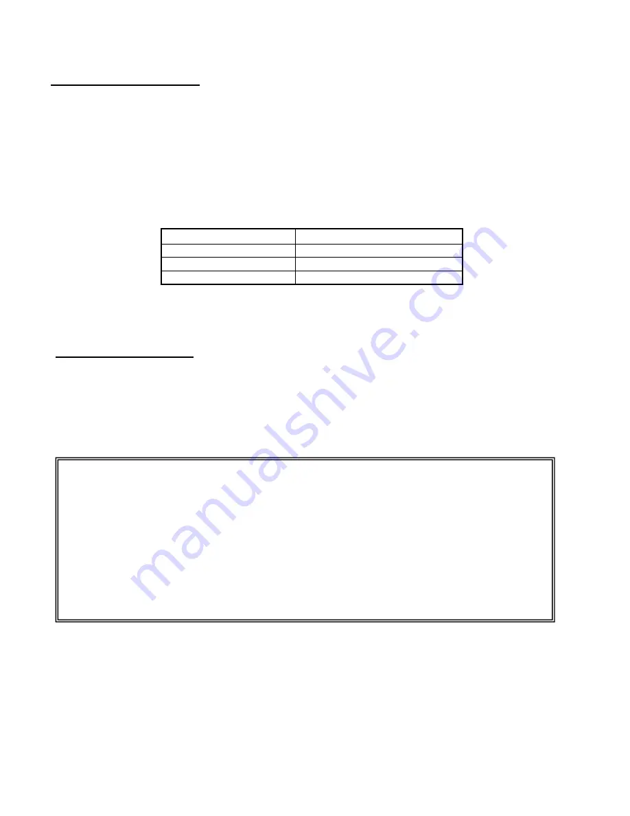
4. Connector coupling nut should be screwed onto Rota-lock spud using the proper amount
of torque.
Spud Size
Amount of Torque
7/8”
50-60 FT LBS
1 1/8”
80-100 FT LBS
1 3/8”
100-110 FT LBS
TABLE 3-6
Rota-lock Connector Torque Ratings
Pressure Relief Valves
Pressure relief valves are installed on the freezer, receiver and the
water cooled condenser. These valves are designed to vent in emergency conditions. This ensures
vessel internal pressure does not exceed maximum allowable pressures.
Vent the relief valve outlet to a safe outdoor location in the approved manner away from people and
building openings. Vent line piping must have drain line at low point to drain condensate from line
per ASME Boiler and Pressure Code, Section VIII, Division 1.
PRESSURE RELIEF VALVES MUST BE REPLACED AFTER 5 YEARS OF SERVICE.
BEFORE REPLACING RELIEF VALVE, REVIEW REQUIREMENTS PER CURRENT
LOCAL AND NATIONAL CODE.
VALVE REPLACEMENT SHOULD BE MADE BY PROPERLY TRAINED PERSONNEL ONLY.
NOTE: IF RELIEF VALVE DISCHARGES, VALVE MUST BE REPLACED AFTER DISCHARGING
BECAUSE SETTING OR SEAT TIGHTNESS MAY BE ALTERED.
CONTACT VOGT ICE PARTS DEPARTMENT FOR REPLACEMENT VALVES.
PHONE: 502-635-3000
Содержание P18FXT
Страница 4: ...Vogt Tube Ice Machines Installation Service Manual and Parts Catalog 12A4171M08 10TA Model ...
Страница 10: ...10TA Service Manual TABLE OF CONTENTS vi BLANK ...
Страница 20: ...10TA Service Manual INTRODUCTION 4 14 14 1 10 BLANK ...
Страница 40: ...10TA Service Manual INSTALLING YOUR TUBE ICE MACHINE 4 14 14 3 18 BLANK PAGE ...
Страница 43: ...10TA Service Manual HOW YOUR TUBE ICE MACHINE WORKS 4 14 2014 4 3 FIGURE 4 1 Water Cooled Piping Schematic ...
Страница 44: ...10TA Service Manual HOW YOUR TUBE ICE MACHINE WORKS 4 14 2014 4 4 FIGURE 4 2 Air Cooled Piping Schematic ...
Страница 50: ...10TA Service Manual START UP AND OPERATION 4 14 14 5 6 BLANK ...
Страница 51: ...10TA Service Manual ELECTRICAL CONTROLS 4 14 14 6 1 6 Electrical Controls FIGURE 6 1 Control Panel SS PB1 PB2 ...
Страница 52: ...10TA Service Manual ELECTRICAL CONTROLS 4 14 14 6 2 FIGURE 6 2 Control Panel Components Standard ...
Страница 60: ...10TA Service Manual ELECTRICAL CONTROLS 4 14 14 6 10 BLANK ...
Страница 111: ...10TA Service Manual 10 7 OPTIONS AND ACCESSORIES FIGURE 10 4 Wiring Schematic Mid Size Machine P112 P118 P18XT ...
Страница 112: ...10 8 10TA Service Manual OPTIONS AND ACCESSORIES BLANK ...
Страница 120: ...10TA Service Manual TABLES CHARTS 7 2 14 11 8 BLANK ...
Страница 124: ...10TA Service Manual INDEX 5 30 14 12 4 ...


