P24AL & P34AL Service Manual
INSTALLING YOUR TUBE-ICE MACHINE
12/2016
3-12
Water Tank Drain.
This valve and connection is for the purpose of flushing and draining the water
tank of impurities, foreign material and cleaning chemicals used during servicing. It should be piped
to an open drain or sump for visible discharge. It can be tied in with the overflow line but no others.
Water Tank Overflow.
A 3” FPT connection on the side of the water tank is provided to carry
away overflow water during the thawing (harvest cycle). This water contains ice fines accumulated
during harvesting and dissolved solids accumulated during the freezing cycle.
Do not reduce the
size of this line
. Three inches is needed to provide sufficient area for ice fines to be flushed out,
especially if the incoming flushing water is 55
F (13
C) or below. This overflow line should not tie
in with any other drain line except the water tank drain.
Unless water quality is superior, do not discharge the overflow water to the cooling tower system.
This water contains additional dissolved solids left from the ice making process and can lead to
excessive condenser fouling or cooling tower chemical usage. It is recommended that a heat
exchanger be used in place of direct contact with condenser water.
Receiver.
The receiver used to supply hot thaw gas must be sized adequately to provide a sufficient
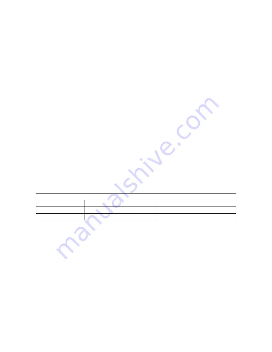
amount of thawing gas to the freezer. Table 3-2 shows the volume required to hold the refrigeration
charge of the freezer and the hot gas required for the thaw cycle. It is recommended that a heating
coil be installed in the receiver to assure that the liquid ammonia is at saturated temperature at the
start of each thaw period.
Note: Additional storage volume may be required for the interconnecting piping. Add volume of
interconnecting piping to the values shown in Table 3-2
RECEIVER VOLUME (Cubic Feet)
MODEL
With Heating Coil
With out Heating Coil
P24AL
30
45
P34AL
50
70
Table 3-2
Receiver Volume Requirements
Thaw Gas Pressure Regulator.
The thaw gas pressure regulator is a 2” solenoid operated pressure
combination regulator and shut-off valve (see Figures 1-2 and 1-5 for locations).
Do not reduce the
size of this line
. This valve is designed to carry the proper amount of thaw gas to the evaporator
during the harvest cycle. See Page 5-7 for operating instructions.
Suction Pressure Regulator.
When a P24AL or P34AL is attached to a central system, a pressure
regulator will be required (see Figures 3-15 through 3-16 for location). This regulator (usually
furnished by the purchaser) must be a combination back pressure regulating and stop-type valve.
The usual minimum pressure drop across this type valve is 2 psig; therefore, the valve must be set to
maintain a freezer pressure that is at least 2 psi above the maximum general suction pressure.
Compressor Unloading.
When a P24AL or P34AL is attached to a dedicated compressor system,
unloading of the compressor will be required. A minimum compressor unloading during the harvest
Содержание P-24AL
Страница 1: ...12 2016 P 24AL P 34AL TUBE ICE MACHINE Service Manual 5000 ...
Страница 10: ...P24AL P34AL Service Manual TABLE OF CONTENTS 12 2016 vi ...
Страница 14: ...P24AL P34AL Service Manual INTRODUCTION 12 2016 1 4 Figure 1 1 P24AL 1 Front Side Control Panel ...
Страница 15: ...P24AL P34AL Service Manual INTRODUCTION 12 2016 1 5 Figure 1 2 P24AL Right Side ...
Страница 16: ...P24AL P34AL Service Manual INTRODUCTION 12 2016 1 6 Figure 1 3 P24AL Back Side ...
Страница 17: ...P24AL P34AL Service Manual INTRODUCTION 12 2016 1 7 Figure 1 4 P24AL Left Side ...
Страница 18: ...P24AL P34AL Service Manual INTRODUCTION 12 2016 1 8 Figure 1 5 P34AL Front Side Control Panel ...
Страница 19: ...P24AL P34AL Service Manual INTRODUCTION 12 2016 1 9 Figure 1 6 P34AL Right Side ...
Страница 20: ...P24AL P34AL Service Manual INTRODUCTION 12 2016 1 10 Figure 1 7 P34AL Back Side ...
Страница 21: ...P24AL P34AL Service Manual INTRODUCTION 12 2016 1 11 Figure 1 8 P34AL Left Side ...
Страница 22: ...P24AL P34AL Service Manual INTRODUCTION 12 2016 1 12 ...
Страница 28: ...P24AL P34AL Service Manual INSTALLING YOUR TUBE ICE MACHINE 12 2016 3 4 Figure 3 2 P24AL Foundation Layout ...
Страница 31: ...P24AL P34AL Service Manual INSTALLING YOUR TUBE ICE MACHINE 12 2016 3 7 Figure 3 4 P34AL Foundation Layout ...
Страница 32: ...P24AL P34AL Service Manual INSTALLING YOUR TUBE ICE MACHINE 12 2016 3 8 Figure 3 5 Lifting Procedure for P24AL ...
Страница 33: ...P24AL P34AL Service Manual INSTALLING YOUR TUBE ICE MACHINE 12 2016 3 9 Figure 3 6 Lifting Procedure for P34AL ...
Страница 53: ...P24AL P34AL Service Manual HOW YOUR TUBE ICE MACHINE WORKS 12 2016 4 3 Figure 4 1 Piping Schematic for P24AL ...
Страница 54: ...P24AL P34AL Service Manual HOW YOUR TUBE ICE MACHINE WORKS 12 2016 4 4 Figure 4 2 Piping Schematic for P34AL ...
Страница 62: ...P24AL P34AL Service Manual START UP OPERATION 12 2016 5 8 ...
Страница 84: ...P24A P34A Service Manual TROUBLESHOOTING 12 2016 8 12 ...
Страница 97: ...P24AL P34AL Service Manual SERVICING OPERATIONS 12 2016 9 13 Figure 9 5B P24A Water Tank Assembly ...
Страница 110: ...P24AL P34AL Service Manual SERVICING OPERATIONS 12 2016 9 26 ...
Страница 126: ...P24AL P34AL Service Manual TABLES CHARTS 12 16 16 11 8 ...
Страница 130: ...P24AL P34AL Service Manual INDEX 12 2016 12 4 ...
Страница 131: ...Appendix A ...
Страница 134: ......
Страница 136: ...i ...
Страница 137: ...ii ...
Страница 138: ...1 ...
Страница 139: ...2 ...
Страница 140: ...3 ...
Страница 141: ...4 ...
Страница 142: ...5 ...
Страница 143: ...6 ...
Страница 144: ...7 ...
Страница 145: ...8 ...
Страница 146: ...9 ...
Страница 147: ...10 ...
Страница 148: ...11 ...


