PFW 6858
Installation Guide
Installationsanleitung, Guía de Instalacíon, Guida de Installazione, Guide d’Installation, Installatie gids
3
4
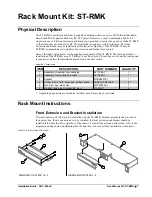
M8 x 10mm Set Screw
CL
Center the cross bar to the display and tighten the two (2) M8 x 10 Set Screws using the
5/32" Allen Key to secure the brackets.
1. Install the Rotational Stop with (3) M6 x 25mm Flat Head Screw.
2. Reversible in either left or right orientation.
M6 x 25mm Flat
Head
Rotational Stop
C
L
O
CKW
I
SE
PRT.
LAND.
PRT.
LAND.
C
O
U
N
T
E
R-
www.vogels.com | Europe +31 (0)40 26 47 400
Page 8