background image

VMAC 

– Vehicle Mounted Air Compressors 

Toll Free:


1-888-241-2289 

Fax: 1-250-740-3201


28 


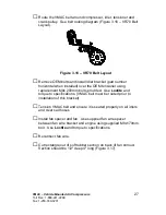
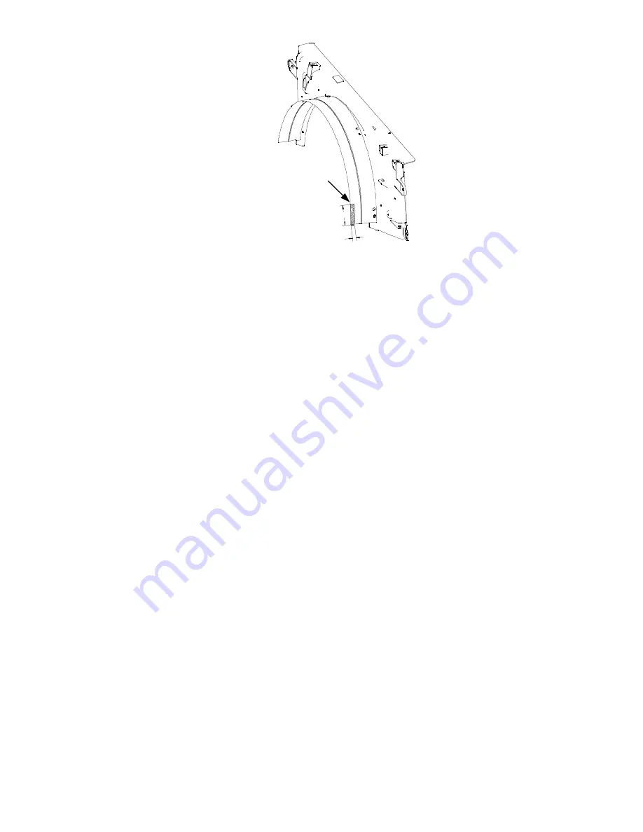
4” 

1/2" 

Remove Shaded 

Area 


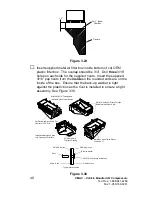
Figure 3.17 

□ 

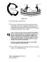
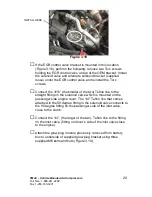
Install upper fan shroud.  Secure power steering reservoir and 
secondary coolant reservoir.   

□ 

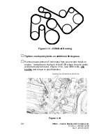
Connect hoses to secondary coolant reservoir.  Route flexible 
upper coolant hose under main compressor bracket across in 
front to the reservoir. Secure hose to A/C line to ensure hose will 
not contact clutch or any other moving components.  

□ 

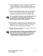
Fill the primary and secondary radiators with saved coolant. 

□ 

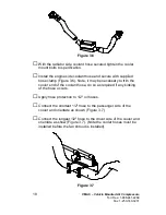
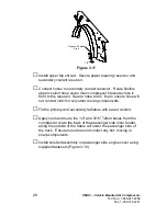
Apply loom and route the 1/4” and 3/16” Teflon hoses from the 
compressor down the back of the passenger side inner fender, 
along the outside of the frame rail under the passenger side of 
the truck.  Ensure hose does not contact any hot, moving or 
sharp components. 

□ 

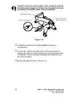
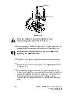
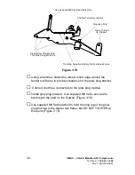
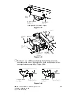
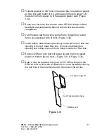
Install solenoid assembly on passenger side engine cover using 
supplied fasteners (Figure 3.18 ) 


Содержание VR70

Страница 1: ...YMAC VEHICLE MOUNTED AIR COMPRESSORS System V90G120 2016 2011 Ford F250 F550 6 7L Diesel www com...

Страница 2: ......

Страница 3: ...y Cable and Relocated Battery Box 31 3 6 Washer Bottle 36 3 7 Air Filter Box 39 Part 4 Installing the Tank and Hoses 51 4 1 Installing the Tank and Brackets 51 4 2 Installing the Hoses 53 4 3 Adding O...

Страница 4: ...r safety is involved While it is impossible to warn about every conceivable hazard let good common sense be your guide This symbol is used to call your attention to additional instructions or special...

Страница 5: ...ranty form is located at the back of this manual This warranty form must be completed and mailed or faxed to VMAC at the time of installation for any subsequent warranty claim to be considered valid T...

Страница 6: ...ly Loctite 242 or equivalent on all engine mounted fasteners Torque values are with Loctite applied unless otherwise specified STANDARD GRADE 8 NATIONAL COARSE THREAD Size 1 4 5 16 3 8 7 16 1 2 9 16 5...

Страница 7: ...MAC warranty form is located at the back of this manual This warranty form must be completed and mailed or faxed to VMAC at the time of installation for any subsequent warranty claim to be considered...

Страница 8: ...of the installation process ensure that the safety and operational instruction decal is affixed in an obvious location so that it can be seen by vehicle operators A good spot for this is usually on t...

Страница 9: ...1 250 740 3201 7 To alert any technicians that may service the vehicle affix the servicing caution contact label in the engine compartment near the hood latch in a visible location Thoroughly clean t...

Страница 10: ...eter to verify the transmission park signal Turn the key to the RUN position do not start the truck as to supply power to the dash display The resistance should read close to 0 ohms in park and open c...

Страница 11: ...od strut ball stud from inner fender Remove positive terminal block and wiring connector panel from passenger side battery box To remove wiring panel pry up Positive terminal block has one clip and sl...

Страница 12: ...ed to passenger side of fan shroud and remove reservoir from fan shroud Remove upper secondary coolant hose top hose going to water pump on passenger side of engine Cut plastic cuff securing hose on s...

Страница 13: ...ing and flexible hose to open end of modified secondary coolant hose Leave about 1 gap between hoses and secure with supplied hose clamps Remove plastic wire guide from front of EGR on passenger side...

Страница 14: ...to upper fan shroud DO NOT remove hose from reservoir Slide reservoir up out of clip securing it to the upper fan shroud Remove 5 bolts 3 on driver s side and 2 on passenger side and wire clips secur...

Страница 15: ...Toll Free 1 888 241 2289 Fax 1 250 740 3201 13 Release tension on OEM belt leave belt routed correctly on passenger side of engine Remove 2 bolts from secondary water pump Figure 2 4 Remove OEM Bolts...

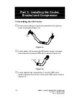
Страница 16: ...y coolant hose attached to the primary cooler and engine Figure 3 1 To Engine From Radiator Figure 3 1 Cut the plastic cuff securing the OEM quick connect to engine side coolant hose discard OEM quick...

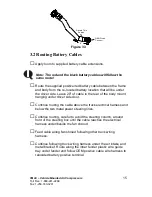
Страница 17: ...0 of cable to the rear of the body mount hanging under driver side door Continue routing the cable above the truck electrical harness and below the two metal power steering lines Continue routing care...

Страница 18: ...of removal the OEM negative battery block bolt should be removed with the engine side coolant hose disconnected Figure 3 4 shown with coolant hose connected to illustrate the OEM negative battery bolt...

Страница 19: ...Cross Member Figure 3 5 Apply Loctite then install bolts through the flat mounting strap and place them on the front of the cross member on each side of the impact sensor Note the impact sensor is loc...

Страница 20: ...lamp Figure 3 6 Note it may be necessary to trim the cooler end of the coolant hose do so as required if any kinking of the hose occurs Apply hose protection to 1 2 oil hoses Connect the shortest 1 2...

Страница 21: ...d flush to top of bolt head then reinstall bolt Figure 3 8 Install main bracket On single alternator trucks use supplied spacers behind top drivers side mount and lower front mount between bracket and...

Страница 22: ...ts and washers provided for front two mounts If installing on a single alternator truck use supplied spacers behind bracket for 130mm bolts Use Loctite and hand tighten only Figure 3 9 Use shorter 40m...

Страница 23: ...studs on Ford F250 F550 Superduty trucks equipped with 6 7L Powerstroke diesel engines as of 29 Sep 11 Figure 3 10 Trucks built after this date may experience clearance issues between the VMAC main b...

Страница 24: ...er pump failure Figure 3 11 Install idlers and tensioner using Loctite and torque to specifications Flex the air condition line that goes over the main bracket in towards the engine to ensure clearanc...

Страница 25: ...cer and install the 4 supplied M12 crank pulley bolts Torque to 22 lb ft will tighten an additional 90 degrees in step to follow Some concerns have been raised regarding the OEM 2011 Ford 6 7 harmonic...

Страница 26: ...ten crank pulley bolts an additional 90 degrees Remove lower portion of inlet brace from air end and install on engine It attaches to the front of the EGR where the wire guide was previously removed F...

Страница 27: ...o tape or cover the opening in the top of the compressor to ensure that nothing can enter the compressor housing as this may cause severe damage to the internal parts or failure of the compressor Bolt...

Страница 28: ...Ensure the brace bracket bolts are not preloaded before tightening the inlet valve bolts Tighten all four 4 inlet valve bolts and torque to specification Tighten the two fasteners joining the brace to...

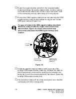
Страница 29: ...tensioner using replacement M8x 200mm bolts provided Use Loctite and torque to specifications VMAC belt must be routed prior to installation of this bracket Tension VMAC belt and ensure it is seated p...

Страница 30: ...front to the reservoir Secure hose to A C line to ensure hose will not contact clutch or any other moving components Fill the primary and secondary radiators with saved coolant Apply loom and route th...

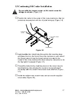
Страница 31: ...ler of the two Teflon line to the straight fitting on the solenoid valve which is mounted on the passenger side engine cover The 1 4 Teflon line that comes attached to the 90 degree fitting in the sol...

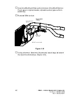
Страница 32: ...ck Nut Negative Post Figure 3 19 Using a hammer flatten the raised rolled edge around the fender sub frame to provide clearance for the glow plug bracket Connect the three connectors to the glow plug...

Страница 33: ...crew the positive lock nut from terminal on glow plug module Modify both OEM battery cable ends positive and negative by removing the threaded stud from the battery cable ends and then enlarging the s...

Страница 34: ...lock nut Connect OEM battery clamp to positive post with the supplied nylock nut Using the supplied tie strap attach the negative battery cable harness to the glow plug module bracket Attach washer b...

Страница 35: ...45 Bolt 3 8 Washer M10 Fender Washer M10 Nut 5 16 x 3 4 Bolts 5 16 Washers 4 Places 5 16 x 2 Bolts 5 16 Washers 2 Places 5 16 Washers 4 Places 5 16 Nuts 2 Places Figure 3 23 Remove 1 of 2 OEM nuts att...

Страница 36: ...ponents and in those cases it is acceptable to relocate the battery to a better location on or in the service body of a truck instead of onto the frame rail See below VMAC cannot list or approve all t...

Страница 37: ...should be used for additional protection The installer must ensure that nothing can be accidentally dropped across the two terminals or have the positive post otherwise shorted to ground If the batte...

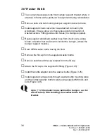
Страница 38: ...Route supplied windshield washer hose from check valve along fender on fender liner and down to behind the bumper where the bumper support mounts Drain OEM washer bottle saving the fluid Remove the f...

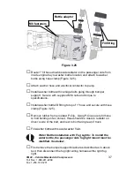
Страница 39: ...ns Install washer bottle fill fitting to top of 1 hose and secure with hose clamp Figure 3 25 Remove rubber from provided P Clip Using P Clip secure fill hose to bolt holding on fan shroud Hose should...

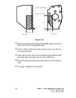
Страница 40: ...y Refer to Figure 3 26 for the area required to be removed from the support bracket After cutting clean and de burr all edges and reinstall for light assembly behind bumper with the three OEM bolts Pl...

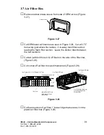
Страница 41: ...filter section Leave the divider intact between the two sections Cut tab with bolt hole in it off flush on the side of the filter box Figure 3 28 Cut corner off air filter box as dimensioned Figure 3...

Страница 42: ...he box Ensure that the back up washer is tight against the plastic box as the rivet is installed to ensure a tight assembly See Figure 3 30 Metal Box Goes Inside Plastic Overlap is 7 Install Rubber In...

Страница 43: ...uide that is clipped into fender frame on passenger side of truck Figure 3 32 Install rubber intake sleeve previously removed from air box into opening in front of metal filter box Groove in rubber fi...

Страница 44: ...r box Foam goes in original location of plastic section groove fits in plastic lip Reinstall OEM air duct CutOffVertical Plastic Tab Forward threaded OEM hole Second threaded OEM hole OEM Air Ductto b...

Страница 45: ...are no sharp edges remaining Remove countersunk fastener holding long leg of the glow plug bracket to inner fender Align UHMW pad supplied with these two holes in inner fender and the large portion o...

Страница 46: ...ure 3 34 Remove hood strut ball stud from passenger side of hood and install into strut relocating bracket Figure 3 35 Install relocating bracket with supplied fasteners as shown Note the 8mm hex nut...

Страница 47: ...d fastener into the new threaded hole above it The brace should sit flush against the firewall with the ground strap on top of the brace Ensure the brace does not make contact with the electrical conn...

Страница 48: ...er Figure 3 37 into second OEM threaded hole in inner fender Figure 3 32 towards rear of air filter box and clamp vertical plastic wall just above air filter box lid slots Front Spacer Supplied Bolt R...

Страница 49: ...Supplied hose OEM filter minder Trim 1 4 of each of the 4 tabs here Figure 3 39 Note If interference is encountered between the air filter lid plastic ribs and mounting hardware or fittings on the com...

Страница 50: ...ter box lid do not tighten Install new air intake tube into rubber elbow end at air box first and then into rubber bellows for engine Figure 3 40 Ensure air box is not pushed down and out of Rear Spac...

Страница 51: ...ompressors Toll Free 1 888 241 2289 Fax 1 250 740 3201 49 Figure 3 41 Ensure intake tube is close to and or resting on the clutch guard rubber pad Loosen hose clamps and adjust tube position if requir...

Страница 52: ...nd adjust tube into rubber elbow if required Add paint pen or other marker to indicate proper alignment once final position is done Figure 3 43 Add paint pen or other marker to indicate proper alignme...

Страница 53: ...ide frame rail behind the suspension radius arm mount Rear Tank Mount Front Tank Mount Suspension Radius Arm Mount Front Note Tank Not Shown For Clarity Figure 4 1 Tank Clips 3 8 x 4 1 2 Bolts 5 16 Nu...

Страница 54: ...sure transducer points towards the top of the tank Install a suitable 3 4 fitting not supplied into the end of the discharge check valve fitting assembly The tank will mount on the passenger side fram...

Страница 55: ...M transmission cross member nut Figure 4 2 Apply Loctite and thread the top bolt into the rear tank mount bracket Ensure the tank clip is hooked over the backside of the frame and no wires or tubes ar...

Страница 56: ...asket contacts the base 4 3 Adding Oil to the System You must use the VMAC supplied and approved compressor oil in this system Failure to use this special oil will result in damage to the compressor a...

Страница 57: ...Bullet Conn WHT DIGITAL GND GRN YEL To pin 3 Purple w green stripe To AOST 3 pin BLK pressure connector To Beacon 2 Pin Conn GRY RED 4 To Buzzer Ring Conn BLK RED To Inlet 2 Pin Conn BRN RED To Temp...

Страница 58: ...ring on the control box harness with 18AWG wiring Solder and seal Crimp the ring terminals provided to the end of the Buzzer wires Extend the blunt cut grey and red BEACON wiring on the control box ha...

Страница 59: ...acket using screws provided in its fastener pack Fasten the relay sockets onto the mount bracket using remaining screws in the fastener pack Install relays into the relay sockets Verify the terminals...

Страница 60: ...ontroller Install the Throttle Controller underneath the dash with nylon ties Route both of its two 6 pin connectors to the foot pedal Connect the 4 pin connector with the mating connector on the wiri...

Страница 61: ...y VMAC Wire To Be Added Shrink Sleeve Soldered Joint Figure 5 3 If the vehicle comes equipped with a hood switch splice and seal the OEM blue w pink hood switch wire with VMAC s grey hood switch wire...

Страница 62: ...tions Connect the Inlet Valve Solenoid on the VR70 Compressor Assembly to its mating connector with red and brown wires on the wiring harness Connect the Clutch on the VR70 Compressor Assembly to the...

Страница 63: ...ay Box in a suitable location with provided screws Mount the Display Box inside the cab or a cabinet protected from extreme weather The Display Box is splash proof but not fully sealed Ensure that it...

Страница 64: ...switched 12V OEM SEIC circuit CDC64 yellow wire with orange stripe on early builds white wire with blue stripe on later builds tachometer signal OEM SEIC circuit CE913 blue wire transmission park sig...

Страница 65: ...ire from the control box to the OEM SIEC circuit CMC25 white wire with a purple stripe at the blunt cut harness Solder and seal the long blue PARK NEUTRAL wire coming from the Throttle Controller to t...

Страница 66: ...the four 4 wires towards the igni0tion connector Connect these wires by matching the colours and labels to the pigtails soldered earlier Yellow wires connect together Orange wires connect together Bl...

Страница 67: ...ie straps Replace all dash panels and other covers removed during installation Install and re connect the batteries Connect cables to battery that was relocated to under driver s side door electrical...

Страница 68: ...p away from and do not interfere with the operation of the park brake mechanism brake accelerator pedals and steering column 6 2 Safety Test Place the vehicle in a safe operating position and block th...

Страница 69: ...mes up to pressure then RPM will settle to the VR Idle RPM This is normal operation With the system running release the Park Brake The system should shut down and the display box show ERRORS DETECTED...

Страница 70: ...firmly on the brake pedal shift the automatic transmission out of PARK and into REVERSE The engine should drop to OEM base idle about 650 RPM Repeat this test in all gear selector positions to make su...

Страница 71: ...operation using the tools that will be operated by the system or you can test operations using an orifice in the outlet to simulate tool use Figure 6 1 Figure 6 1 Install the test tool in the tank out...

Страница 72: ...gauge begins to drop Engine speed should start to ramp up when air pressure drops to approximately 140 psi 6 4 Auxiliary Air Receiver If you intend to use an auxiliary air receiver with this system yo...

Страница 73: ...Adds atomized tool oil to lubricate tools Reduces pressure for longer tool life Hose Reel Part Number A700007 Secure compact retractable hose storage in a sturdy reel Air Receiver Tank Part Number A30...

Страница 74: ...This page intentionally left blank...

Страница 75: ...This page intentionally left blank...

Страница 76: ...This page intentionally left blank...

Страница 77: ...This page intentionally left blank...

Страница 78: ...y _____________________ State Prov ______________ Installation Date _____ _____ _____ Day Month Year Owner Information Company Name ______________________________________ Address _____________________...

Страница 79: ......
Страница 80: ...Ma n u f a c t u r e db y P H2 5 0 7 4 0 3 2 0 0 F X2 5 0 7 4 0 3 2 0 1 T F1 8 0 0 7 3 8 8 6 2 2 1 3 3 3K i p pR o a d N a n a i mo B C V 9 X1 R 3C a n a d a w w w v ma c a i r c o m...

Отзывы: