Viz 2110 I/O Module Operating Instructions
5
SECTION 1.5
NETWORKING
1.5.1
ETHERNET
Generally, simply connecting a suitable cable from one of the two Gigabit Ethernet ports on the backplane is
all that is required to add it to a
local area network
(LAN), which typically will serve for NDI I/O connections
as well as more mundane networking chores. In some settings, additional steps may be required. You can
access the system
Network and Sharing
control panel to accomplish more extensive configuration tasks. If
further help connecting is required, please consult your system administrator.
1.5.2
SFP A AND B (SMPTE 2110)
The two MSA compatible SFP cages (identified as SFP A
and B; see #5 in Figure 1) are provided.
This is where you will plug in your preferred SFP (Small
Form-factor Pluggable) transceivers to connect and
serve SMPTE 2110 traffic between external systems and
your Viz 2110 I/O IP.
Each of the two SFP connection allows two SMTPE 2110
input connections (for a total of four) and two outputs to
SMTPE 2110.
SECTION 1.6
CONFIGURATION
(ADMINISTRATION)
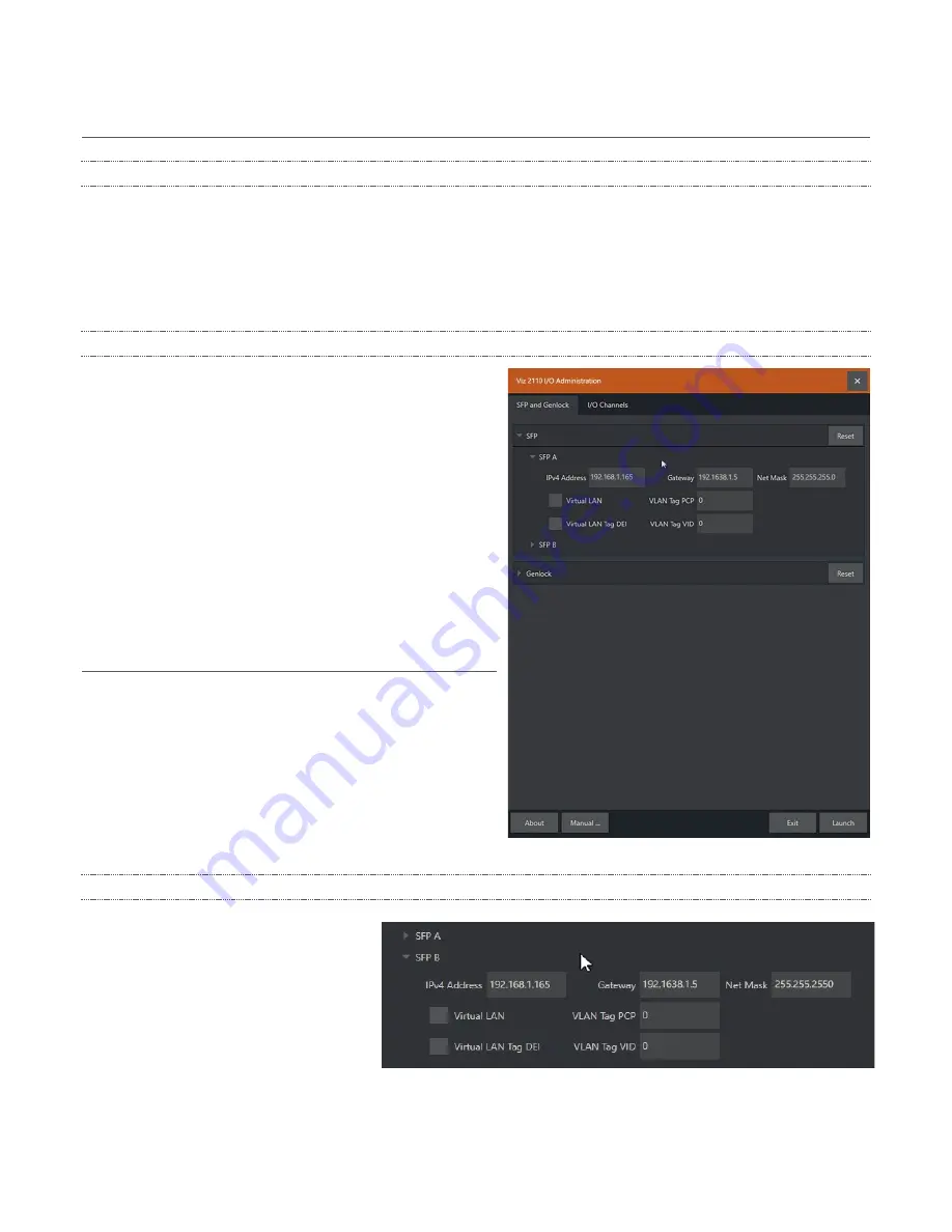
The configuration of the two SFP ports, Genlock, and
(SMPTE 2110)
I/O Channels
is performed in Viz 2110 I/O
IP’s
Administration
panel, shown in (Figure 2).
This control panel appears on first launch, and thereafter
can be accessed by selecting
Exit to Admin
from the
Desktop
(see Section 2.2.1), or from the Windows start
menu.
1.6.1
SFP CONFIGURATION
Click the
SFP and Genlock
tab and the
header (A or B) for the SFP you wish to
configure to expand its settings group.
As a minimum, you will need to supply
the following values in order to identify
the SFP connection on the network you
wish to connect it to:
FIGURE 2
FIGURE 3


