background image

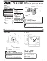
Getting to know your thermostat

Glow in the dark light button
Fan Key

System Key

Setpoint buttons

Menu button

LCD Display

Gently slide a screwdriver into the 

bottom edge of the badge. Gently 

turn the screwdriver counter 

clockwise.  The badge is held on by 

a magnet in the well of the battery 

door.  The badge should pry off easily. 


DO NOT USE FORCE.

About The Badge

All of our thermostats use the same universal magnetic badge.  Visit the 

company website to learn more about our free private label program.

Private Label Badge

Thermostat Quick Reference

7

8

11

12

Wiring Diagrams

Wiring Diagrams

Typical 2H/2C System: 1 Transformer

Typical 2H/2C System: 2 Transformer

Typical 3H/2C or 2H/1C Heat Pump System

Typical Heat-Only System

Typical Heat Only System With Fan

Typical Cool-Only System

HEAT RELAY

RC
RH

Y
C

W/E

G

C

R

L2

L1

(HOT)

FAN RELAY

HEAT RELAY

RC
RH

Y
C

W/E

G

C

R

L2

L1

(HOT)

FAN RELAY

COMPRESSOR 

RELAY

C

R

L2

L1

(HOT)

RC

RH

Y
C

G

Power supply
Factory-installed jumper.  Remove only when installing on 2-transformer systems

Use either O or B terminals for changeover valve
Optional 24 VAC common connection when thermostat is used in battery power mode

W/E

RC
RH

Y
C

W/E

G

W2

Y2

COMPRESSOR

RELAY

FAN RELAY

AUXILIARY

HEAT RELAY 

COMPRESSOR

RELAY 2

COOL CHANGE

OVER VALVE

HEAT CHANGE

OVER VALVE

C

R

L2

L1

(HOT)

REMOVE JUMPER 

RC
RH

Y
C

W/E

G

W2

Y2

C

R

L2

L1

(HOT)

C

R

L2

L1

(HOT)

COMPRESSOR

RELAY

HEAT RELAY

FAN RELAY

HEAT RELAY 2

COMPRESSOR

RELAY 2

RC
RH

Y
C

W/E

G

W2

Y2

COMPRESSOR

RELAY

FAN RELAY

HEAT RELAY 2

COMPRESSOR

RELAY 2

HEAT RELAY

C

R

L2

L1

(HOT)

O
B

EMERGENCY 

HEAT RELAY

Magnet in door

Use the bevel on lower ridge

3

2

1

1

2

3

Note:

In many systems with no emergency heat relay a jumper can be installed 

between W/E and W2.

Содержание TP-S-955CR

Страница 1: ...sh with the wall 4 Wires should be pushed into the wall Installation Tips The thermostat should be installed approximately 4 to 5 feet above the floor Select an area with average temperature and good...

Страница 2: ...mpressor delay feature is active if these icons are flashing The compressor will not turn on until the 5 minute delay has elapsed Setpoint Displays the user selectable setpoint temperature HOLD is dis...

Страница 3: ...calCool OnlySystem HEAT RELAY RC RH Y C W E G C R L2 L1 HOT FAN RELAY HEAT RELAY RC RH Y C W E G C R L2 L1 HOT FAN RELAY COMPRESSOR RELAY C R L2 L1 HOT RC RH Y C G Power supply Factory installed jumpe...

Страница 4: ...ation is adjustable A smaller swing setting will cause more frequent cycles and a larger swing setting will cause fewer cycles Cooling Swing The cooling swing setting is adjustable from 0 2 to 2 For e...

Страница 5: ...fan during a call for heat Select ELEC to have the thermostat control the fan during a call for heat Fan Operation GAS or ELEC GAS GAS FAN SET Reminders Once a reminder has been turned on and set the...

Страница 6: ...D1 OCCUPIED 2 UNOCCUPIED 2 Repeat steps 4 through 7 for the remaining days of the week A Note About Auto Changeover In Auto you have the ability to switch between Auto Heat or Auto Cool by pressing th...

Страница 7: ...ith the fan key 5 Then use the or key to make your setpoint selection for the weekday OCCUPIED period 6 Press Next 7 Repeat steps 4 through 7 for the weekday UNOCCUPIED time period To customize your 5...

Страница 8: ...porary Permanent Hold Feature Filter Change Other Reminders If your installing contractor has configured the thermostat to remind you when the air filter needs changed you will see a reminder in the d...

Отзывы: