


A/A DC INVERTER U-MATCH AIR CONDITIONERS MAINTENANCE
141
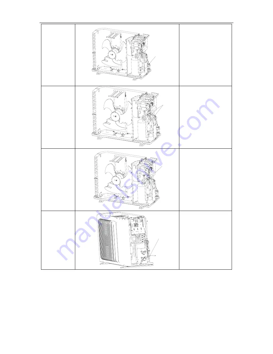
5. Place the new
compressor on
the base
a. Put the new compressor
in the right place.
b. Tighten the screws of the
compressor with a wrench
c. Never put the compress
upside down
6. Connect the
suction/discharge
pipes of the
compressor with
the system
piping.
a. Connect the
suction/discharge pipes of
the compressor by means of
gas welding.
b. During the welding,
nitrogen should be inflated
and its pressure should be
0.5±0.1kgf/c
㎡
(relative
pressure)
c. Attention should be taken
during the heating to avoid
the surrounding objects
burnt due to the high
temperature.
7. Connect the
power cord of the
compressor
a. Connect the power cord
as the reverse way of
disconnection mentioned
above.
b. Tighten the cover of the
compressor with a screw
driver.
8. Establish
vacuum through
liquid valve
Establish vacuum inside the
system through liquid valve.
Содержание ACP-12CC35GECI
Страница 2: ......
Страница 3: ...GREE COMMERCIAL AIR CONDITION A A DC INVERTER U MATCH AIR CONDITIONERS 1 PRODUCT ...
Страница 15: ...GREE COMMERCIAL AIR CONDITION A A DC INVERTER U MATCH AIR CONDITIONERS 22 CONTROL ...
Страница 16: ...A A DC INVERTER U MATCH AIR CONDITIONERS CONTROL 23 CONTROL 1 OPERATION FLOWCHART 1 1Cooling Dry Operation ...
Страница 17: ...A A DC INVERTER U MATCH AIR CONDITIONERS CONTROL 24 1 2 Heating Operation ...
Страница 52: ...GREE COMMERCIAL AIR CONDITION A A DC INVERTER U MATCH AIR CONDITIONERS 59 5 3 7 Dimensions ...
Страница 53: ...GREE COMMERCIAL AIR CONDITION A A DC INVERTER U MATCH AIR CONDITIONERS 60 INSTALLATION ...
Страница 76: ...GREE COMMERCIAL AIR CONDITION A A DC INVERTER U MATCH AIR CONDITIONERS 99 MAINTENANCE ...
Страница 95: ...A A DC INVERTER U MATCH AIR CONDITIONERS MAINTENANCE 118 IPM module protection ...
Страница 96: ...A A DC INVERTER U MATCH AIR CONDITIONERS MAINTENANCE 119 DC busbar overvoltage protection ...
Страница 97: ...A A DC INVERTER U MATCH AIR CONDITIONERS MAINTENANCE 120 DC busbar undervoltage protection ...
Страница 98: ...A A DC INVERTER U MATCH AIR CONDITIONERS MAINTENANCE 121 Abnormal noise from PFC inductor ...
Страница 99: ...A A DC INVERTER U MATCH AIR CONDITIONERS MAINTENANCE 122 Radiator overheat protection ...
Страница 100: ...A A DC INVERTER U MATCH AIR CONDITIONERS MAINTENANCE 123 Tripping ...
Страница 172: ...A A DC INVERTER U MATCH AIR CONDITIONERS MAINTENANCE 224 Model ACP 24CC70GECI ACP 24CF70GECI Exploded View ...
Страница 176: ...A A DC INVERTER U MATCH AIR CONDITIONERS MAINTENANCE 242 Model ACP 12CC35GECI Exploded View ...
Страница 178: ...A A DC INVERTER U MATCH AIR CONDITIONERS MAINTENANCE 244 Model ACP 18CC50GECI Exploded View ...
Страница 182: ...A A DC INVERTER U MATCH AIR CONDITIONERS MAINTENANCE 249 Model ACP 36CC100GECI Exploded View ...
Страница 188: ......
Страница 189: ......
Страница 190: ......


