EN
33
connector and the inlet connector to
ensure the seal;
3. Tighten the locking nut on the outlet
connector;
The suction hose must be
reinforced (steel mesh or wall
that does not allow folding) in order to
avoid collapse during the operation of
the motor pump. Do not use hose with
a smaller diameter than the inlet hose.
3.3 - MOUNTING THE OUTLET /
DISCHARGE HOSE (FIG.F)
1. Insert the end of the outlet / discharge
hose into the outlet pipe (7) and attach
the clamp provided with the motor
pump;
2. Place the rubber gasket between the
connector and the inlet connector to
ensure the seal;
3. Tighten the locking nut on the outlet
connector (7);
4. OPERATING
INSTRUCTIONS
4.1 - PUMP START (FIG.G)
1. Remove the filler cap (12) from the
outlet connector;
2. With the filter / spout immersed and
the suction hose placed in the motor
pump, fill the pump chamber (8) with
clean water through the filling hole. The
chamber is full when water begins to
leak into the outlet pipe (7);
3. Start the engine and check that the
pump draws in water
4. If the pump does not suck water stop
the pump immediately;
5. Ensure that the hose and connections
to the intake pipe in the pump are
properly sealed and repeat the above
steps until the pump is primed;
Always make sure that the pump
chamber (8) is filled with water
before starting the engine. Operation of
the pump without water will cause
damage to the pump seal.
4.2 - STARTING THE ENGINE
(FIG.H)
1. Close the air, move the air lever (4)
until it touches the top;
2. Press the carburetor pump (17)
several times until it is filled with
gasoline, at which point the carburetor
is fueled;
3. set the throttle lever (13) midway
between positions;
4. Pull the starter handle (3) slowly
until you feel some resistance, then pull
hard until the engine starts;
5. After approx. 30s, open the air,
move the air lever (4) until it clicks
down.
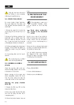
Do not close the air if the engine
is warm or the air temperature is
high.
4.3 - ENGINE STOP (FIG.I)
1. Set the throttle lever (13) to the left;
2. Press the stop button (19);
In an emergency, press the stop
button immediately;
4.4 - THROTTLE ADJUSTMENT
(FIG.J)
The engine speed is adjusted via the
throttle lever (13).
With the throttle lever turned to the
left, the engine runs at idle. The speed
increases as the lever is moved to the
right.
4.5 - FUEL (FIG.K)
The engine should run on a mixture of
unleaded petrol and engine oil in the
proportion of 1:40 (1L of oil for two-
stroke engines per 40L of gasoline).
Put the 2-stroke engine oil first in a
fuel-approved container and then add
gasoline, thoroughly mix.
Unsuitable fuel or other than the
recommended proportion may lead to
severe engine damage. Lower quality
petrol or oil can damage the engine,
sealing rings, hoses, and fuel tank.
Store the fuel mixture in
approved, fuel-efficient
containers in a safe, dry and cool place
protected from light and sun. The fuel
mixture ages, mix only the amount
needed for a few weeks.
Shake the fuel mixture tank before
filling the machine tank.
In the tank pressure can be
formed, open the tank with care.
Avoid direct skin contact and inhalation
of combustible vapors. When filling the
fuel tank (2), do not add fuel above the
minimum level of the filling nozzle.
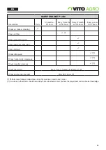
5. MAINTENANCE
INSTRUCTIONS
Before any maintenance or
cleaning work, place the motor
pump on a level surface, and remove
the spark plug pipe (14).
5.1 - CLEANING THE AIR FILTER
(FIG.L)
1. Remove the tightening screw and
filter cover (15);
2. Remove the filter element and blow
it off with compressed air until it is
completely clean;
3. Insert the filter element and
assemble the remaining components in
the reverse order of disassembly;
Содержание VIMB12TA
Страница 49: ......
Страница 50: ...RUA DA GÂNDARA 664 4520 606 S JOÃO DE VER STA MARIA DA FEIRA PORTUGAL MI_VIMB12TA_REV00_JAN18 ...

