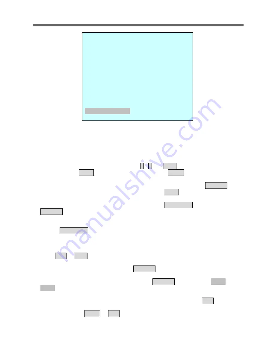
background image

VT-PTZ12 


23 


Focus    I : IRIS   

F  : 

B  :  BLC


X  : 

16 digit of preset title 

-

  : 

not defined 

  : 

Current cursor position   

 
Follow the steps below to program the Preset positions. 

1. Select the camera number by pressing 

0

 ~

9

 and 

CAM

2. Simply press 

PRST

 button to enter preset menu. ( 

MENU


=> FUNCTIONS => 

PRESET

3. Select the empty preset location to be programmed by moving the 

Joystick


up/down. If selected location is not empty, pressing 

PRST

 button will display the 

predefined position. 
4. After selecting an empty position, press and hold 

SHFT/PGM

 then use the 

Joystick

 to control the direction of the camera and lens.(Or twist the zoom handle or 

press the zoom button to start PTZ control for view selection.)  
5. After aiming the camera (view direction and lens control) to a specific position, 
release 

SHFT/PGM

 button (or hit the focus button).  The selected location No. field 

will be filled with “

A A F

”. Move the joystick to the right to select each Focus/ Iris 

/BLC mode using zoom handle. 
6. Move to the title field to edit/enter the name. Rotate the handle CW and CCW or 
press 

Tele

 or 

Wide

 button to scroll through the alphanumeric characters.  Moving 

the handle to right or left to select next or previous digit. 
7. To finish entering the title, move the 

Joystick

 up/down.  

8. Locate the cursor on “

PREV NEXT”

 item


to select the previous/next page of 

presets, scroll through the page by moving the 

Joystick

 to the Left on “

PREV   

NEXT”

9. Repeat the steps 2 through 8 for each additional preset position. 
10. Select 

Save and Exit

 by moving the Joystick to the right. Press 

ESC

 to exit the 

Preset menu without saving. 

NOTE: Press the Home or OFF button at programmed position to delete the 
preset.


PRESET                    01/8 


NO. F I B  TITLE 

001 A A F  xxxxxxxxxxxxxxxx 
002 M M O  ---------------- 

003 - - -  ---------------- 

004 - - -  ---------------- 

005 - - -  ---------------- 

006 - - -  ---------------- 
007 - - -  ---------------- 

008 - - -  ---------------- 

PREV      NEXT 

SAVE AND EXIT


Содержание VT-PTZ12W

Страница 1: ...slow to medium panning with smooth Diagonal Scan 4 Tours Each tour consists up to 32 Presets Patterns and or Scans Fully Gasket Sealed IP 66 Rated Weatherproof Design 4 Alarm inputs with 1 4 priority...

Страница 2: ...me camera please make sure that the following items are included in the box 1 Mini Speed Dome Camera 2 Instruction Manual 3 Mounting Hardware If any of these materials are missing please contact the v...

Страница 3: ...ware and software described herein at any time without prior notice No part of this guide may be reproduced transmitted transcribed stored in a retrieval system or translated into any language in any...

Страница 4: ...lash with arrowhead symbol within an equilateral triangle is intended to alert the user to the presence of uninsulated dangerous voltage within the product s enclosure that may be of sufficient magnit...

Страница 5: ...L MAY CAUSE HARMFUL INTERFERENCE TO RADIO COMMUNICATIONS OPERATION OF THIS EQUIPMENT IN A RESIDENTIAL AREA IS LIKELY TO CAUSE HARMFUL INTERFERENCE IN WHICH CASE THE USER WILL BE REQUIRED TO CORRECT TH...

Страница 6: ...t of the obsolete outlet 9 Protect the power cord from being walked on or pinched particularly at plugs convenience receptacles and the point where they exit from the equipment Only use attachments ac...

Страница 7: ...31 3 3 3 NORTH DIRECTION MENU SCREEN NORTH DIRECTION 32 3 4 CAMERA MENU CAMERA 34 3 4 1 FOCUS CONTROL MENU CAMERA FOCUS CONTROL 34 3 4 2 WB white balance MENU CAMERA WB CONTROL 35 3 4 3 AE CONTROL MEN...

Страница 8: ...VT PTZ12 6...

Страница 9: ...to medium panning with smooth DiagonalScan 4 Tours Each tour consists up to 32 Preset Pattern and Scan Smooth DiagonalScan mode and programmable Individual dwell time camera functions Speed Dwell tim...

Страница 10: ...oystick controllers and a variety of external switching devices such as multiplexers MUXes and Digital Video Recorders DVRs may be incorporated to accommodate the needs from a small to a large surveil...

Страница 11: ...NITOR AC 24V POWER HALF DUPLEX MODE TRX TRX TRX TRX CONTROLLER DOME POW ER AC 24V AC 24V HEATER 1 AUX OUTPUT 4 ALARM INPUT C O M M T R X T R X RS 485 2 2 Basic Configuration of Speed Dome Camera Syste...

Страница 12: ...e the RS485 conductor wire from the Speed Dome Camera Connect the into the TRX TRX ports of the DVR Tx Tx ports can be found in the rear part of the DVR Figure 3 Camera into DVR 2 4 Connecting the Spe...

Страница 13: ...VT PTZ12 11 2 5 Connecting Both Speed Dome and DVR via J box Figure 5 Connecting Camera DVR into Controller...

Страница 14: ...Protocol The dome camera must be installed by qualified service personnel Before installing the dome camera system this instruction manual must be read thoroughly and understood fully Dome cameras mu...

Страница 15: ...Run Wiring Home run wiring forms a star shape Each camera connects to one central location on the star That central location is usually the junction box of a keyboard or may also be the RS 485 input t...

Страница 16: ...VT PTZ12 14...

Страница 17: ...ical to the camera port of the DVR SW1 Termination ON SW Termination ON TERMINATION ON SW1 Termination ON DVR Termination ON S1 Dome1 port Termination ON S1 Dome1 port Termination ON SW1 Termination O...

Страница 18: ...switch settings Note Consult service personnel if a dome camera is installed with a device other than a recommended Speed Dome Controller Figure 10 Protocol Selection tables 2 9 Connections How to Co...

Страница 19: ...can be used to signal the dome camera reacting to an event See Chapter 3 2 Program and Operation for configuring alarm input GND Ground NOTE All the connectors marked GND are common Connect the ground...

Страница 20: ...gned to mount on a structural body supporting loads up to 3 Kg See Figure 11 Figure 11 Example of a flush mounted installation 3 1 Power on and Boot up Sequence Installation Hint Using Four ST4X30 scr...

Страница 21: ...creen Display in normal control mode RAM TEST CHECK NO OK CHECK AAAA OK CHECK 5555 OK XPRESS DOME Vx xxx ID 0001 9600BPS AUTO CAMERA TYPE xxxx TILT ORIGIN SET OK PAN ORIGIN SET OK INITIAL CAMERA OK 00...

Страница 22: ...le of joystick usage in the programming editing mode Button or Joystick movement in menu Function Joystick left or right Go into the sub menu items Execute the command exit Change value Navigate throu...

Страница 23: ...ion FUNCTION Tour Preset Pattern Autoscan NUMBER TIME 10 240 Seconds OPERATION DISABLE The HOME function applies to the predefined functions such as Preset Tour Pattern or Scan function after the keyb...

Страница 24: ...CW CW or twist the joystick to right left to set waiting time 8 Highlight OPERATION option by pulling the Joystick down Choose operation status Enable or Disable by moving the Joystick to the right or...

Страница 25: ...tton or hit the focus button The selected location No field will be filled with A A F Move the joystick to the right to select each Focus Iris BLC mode using zoom handle 6 Move to the title field to e...

Страница 26: ...60 seconds of total recording space Stored pattern is played back by pressing No PTRN buttons subsequently Follow the steps below to program the Pattern 1 Press MENU key to display the main menu on th...

Страница 27: ...d pattern NOTE If total recording time reaches 120 seconds it will automatically stop for a moment and start recording again Previous data will be overwritten 3 1 4 SCAN MENU FUNCTIONS SCAN or Shortcu...

Страница 28: ...on to start PTZ control for view selection and hit the Focus button to stop 5 Move the Joystick downward to select END ANGLE Hold down the SHFT PGM key while moving the Joystick to select the end posi...

Страница 29: ...03 Preset 07 Pattern 01 Tour 04 Preset 08 Preset 05 Pattern 01 Tour1 executes as follows Preset 02 Preset 03 Preset 05 Preset 06 Preset 05 Preset 07 Pattern 01 Repeat Tour 04 in Tour 02 will be skippe...

Страница 30: ...Step 2 through 4 for each desired position Each title will be displayed on top of the line 6 Up to 8 Presets Tours Patterns Scans can be selected for a Tour You can expand the Tour sequence by calling...

Страница 31: ...larm will be held for programmed time 01 to 99 seconds LATCH ON Shows all alarms including past alarm OFF Shows activated alarms only There are 5 levels of priority 0 Highest priority supports repeate...

Страница 32: ...reset number or to change the status or output number twist the Joystick clockwise or counterclockwise In case of preset programmed preset number will be scrolled 5 Locate the cursor on Save and exit...

Страница 33: ...ption by moving Joystick Up or Down and move the joystick to right to enter the detail menu 2 Select the privacy zone number by moving the Joystick up or down 3 To enter the zone name rotate the handl...

Страница 34: ...button to delete programmed privacy zone 3 3 3 NORTH DIRECTION MENU SCREEN NORTH DIRECTION Move the joystick handle to the right to select NORTH DIRECTION options 1 Select DISPLAY option to turn on o...

Страница 35: ...XT go to previous page or next page of the menu 6 Save and exit the program by moving the Joystick to the right Press ESC to exit the program without saving 3 3 5 CAMERA TITLE MENU SCREEN CAMERA TITLE...

Страница 36: ...ERA MENU FOCUS CONTROL WB CONTROL EXPOSURE SETUP BACK LIGHT OFF SHARPNESS 31 DIGITAL ZOOM OFF 2X 4X MAX NIGHT SHOT CAMERA INITIALIZE SAVE AND EXIT 3 4 1 FOCUS CONTROL MENU CAMERA FOCUS CONTROL MODE AU...

Страница 37: ...for a moment the lens moves to adjust the focus for the subject The focus lens then holds that position until the Joystick handle rotation 3 4 3 AE CONTROL MENU CAMERA EXPOSURE SETUP BRIGHT 0 100 IRI...

Страница 38: ...tical zoom only 2x 4x Max Digitally magnifies up to 2x 4x 10x respectively 3 4 7 NIGHT SHOT MENU MENU CAMERA NIGHT SHOT The NIGHT SHOT option removes the IR Cut filter of the camera and makes the came...

Страница 39: ...E AND EXIT 3 5 1 FLIP MENU SETUP FLIP When the Speed Dome camera is mounted on a ceiling it can track a moving target in a path directly below the camera ON When the camera reaches the moving object d...

Страница 40: ...he tilting range by up to 10 degree on both ends During zoom out operation the tilting range is increased slightly by additional 10 degree 3 5 6 CALIBRATION MENU SETUP CALIBRATION RESET ORIGIN Calibra...

Страница 41: ...ammed data in the EEPROM of the selected dome camera Press MENU or ENTER button to erase data ESC key to exit without erasing Origin offset value is not affected CAUTION Unless you download the data i...

Страница 42: ...o 44mm F1 6 to F2 5 View angle Approx 48 WIDE end to 2 8 TELE end Optical Zoom 12x Digital Zoom 12x Shutter Speed 1 1 1 10 000 S N ratio more than 50dB Sync System Int Ext V Phase Remote Control Scann...

Страница 43: ...c 380 sec Proportional Pan Tilt YES Communication RS 485 baud rate 2400 38400bps default 9600bps Preset 128 positions with camera status 16 character title Zone Title 24 Area Names Privacy Zone 8 Bloc...

Страница 44: ...quipments in the system and refer to the equipment manual for further information Problem Solution No video Verify that power is connected to all components in the system Verify that the power switche...

Страница 45: ...CONTROL AGC Allows for the amplification of the video signal in scenes with minimal ambient light Many low light scenes result in picture noise As gain is increased the picture noise is also amplified...

Страница 46: ...era Typical input devices include door contacts motion detectors and smoke detectors IR MODE A feature of the camera that permits manual or automatic switching between color and IR black and white ope...

Страница 47: ...era SHUTTER LIMIT Setting used to define the maximum exposure time for the Open Shutter setting The values for the setting range from 1 2 to 1 60 The default setting is 1 4 WHITE BALANCE Adjustments i...

Страница 48: ...irement Dimension W x H 1 4 Interline Transfer CCD Sony 550 TV Lines 0 6 lux 0 01 lux ICR ON 3 7mm to 44mm F1 6 to F2 5 Approx 48 WIDE end to 2 8 TELE end 12x 12x 1 1 1 10 000 more than 50dB Int Ext V...

Страница 49: ...a defective product however all related costs including but not limited to shipping and or delivery charges will be the responsibility of the customer If upon return inspection a product is determined...

Страница 50: ...28492 Constellation Road Valencia ca 91355 WWW VITEKCCTV COM 888 VITEK 70...

Отзывы: