J U N C T I O N B O X J B 4 4 X X - M A N U A L
20120608
FRABA VITECTOR GmbH
5 / 6
Carlswerkstr. 13 C · D - 51063 Köln
Tel.: +49 (0) 221 - 9 62 13-85, T49 (0) 221 - 9 62 13-60, www.vitector.eu
EN
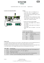
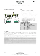
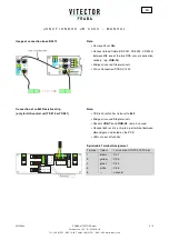
Use of PCB with 4-lead Spiralcable
O
S
E
-T
x
O
S
E
-R
x
S
T
x
Power
OSE-Function
Short Circuit
Tx - wh 1
bn 2
gn 3
Rx - wh 4
O
S
E
ON
12
O
S
E
-
8
k2
4p
o
l -
5
po
l
1
-
b
n
2
-
y
e
3
-
g
n
4
-
w
h
1
-
g
y
Stop
Stop
Note
:
•
Switch 4pol – 5pol has to be set to
4pol
•
Switch OSE – 8k2 has to be set to
OSE
•
Bridge all unused Stop terminals
•
Use 4-pole-connector if sensors to connect come
with blank wires (otherwise use sockets as shown)
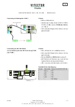
Connect sensors with blank wires as follows:
•
Join green wires and connect to terminal 3 (gn)
•
Join brown wires and connect to terminal 2 (bn)
•
Connect white wires of each sensor separately to
terminals 1 and 4 (wh)
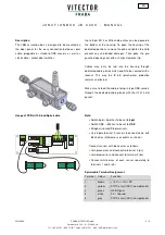
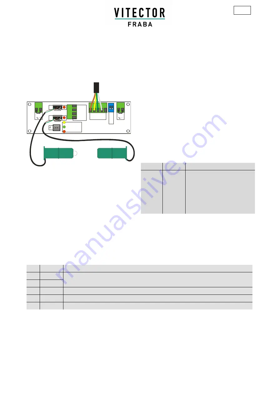
Spiralcable Terminal Assignment
Terminal Colour
Function
1
brown
+12 V (+/-10%) DC
2
yellow
STOP-circuit (NCC) to +12V
(terminal 1)
3
green
OSE-Signal
4
white
0 V / Ground
5
grey
unused
Diagnostic LED
To indicate the function and quick detection of errors, the PCB is equipped with five LEDs. During normal operation the
yellow LED (power) and the green LED (OSE-function) will be lit. An almost unnoticeable flickering of the green LED
during operation is considered normal.
The two red LEDs next to the sensor connectors indicate the power consumption of each sensor. If sensors with
extremely low power consumption are connected, the red LEDs may start to glow lightly.
LED Status
Possible Cause
1
on, red
the corresponding sensor is not working. Check the connection and the condition of the cable, for
malfunctions or damages, otherwise exchange the sensor. LEDs are off during normal run
2
on, red
3
on, yellow Power 12V
4
on, green OSE-function, when blinking slowly or off check rubber profile for possible damages
5
on, red
Short circuit


