J U N C T I O N B O X J B 4 4 X X - M A N U A L
20120608
FRABA VITECTOR GmbH
4 / 6
Carlswerkstr. 13 C · D - 51063 Köln
Tel.: +49 (0) 221 - 9 62 13-85, T49 (0) 221 - 9 62 13-60, www.vitector.eu
EN
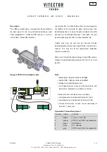
Description
The JB44xx junction box is designed to be mounted on
the door panel for the easy connection between spiral
cable, pluggable or standard OSE-sensors as well as
slack-cable- / wicket door switches.
.
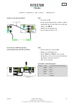
Up to 5 pcs M12 or M16 cable entries can be opened in
the bottom of the housing. To open the housing at the
dedicated positions, remove the pcb and tighten the lid to
prevent any unintended damages. Then poke the pre-
punched openings out with a sharp screwdriver tip.
Cables may only be fed into the housing through
dedicated cable glands which ought to be secured with a
locknut. This way the IP 65 splash-water protection
remains unaffected.
Make sure to feed the cable of plug-in type OSE-sensors
through the dedicated cable glands with the slit Ø 3 mm
gasket.
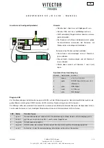
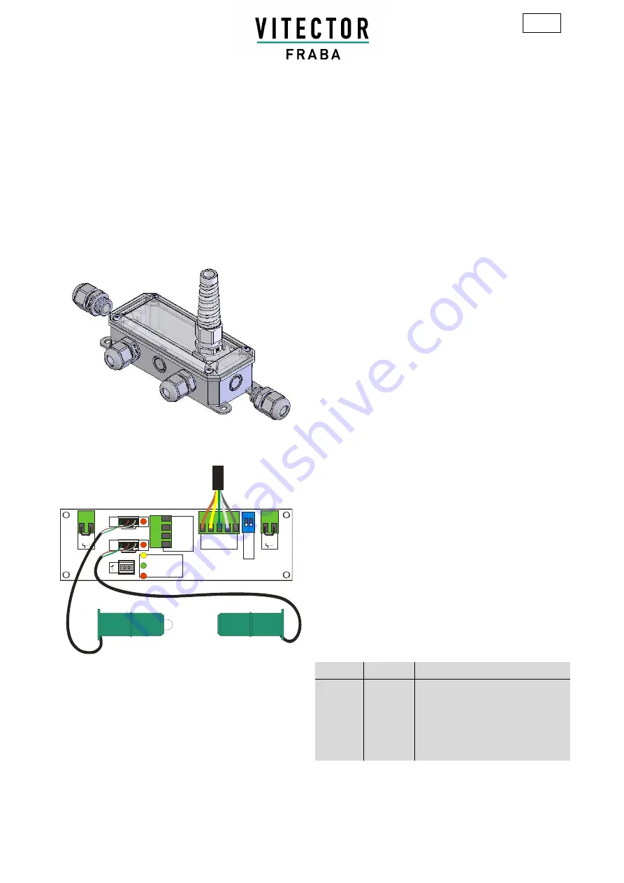
Usage of PCB with 5-lead Spiralcable
O
S
E
-T
x
O
S
E
-R
x
S
T
x
Power
OSE-Function
Short Circuit
Tx - wh 1
bn 2
gn 3
Rx - wh 4
O
S
E
ON
12
O
S
E
-
8
k2
4p
o
l -
5
po
l
1
-
b
n
2
-
y
e
3
-
g
n
4
-
w
h
1
-
g
y
Stop
Stop
Note
:
•
Switch 4pol – 5pol has to be set to
5pol
•
Switch OSE – 8k2 has to be set to
OSE
•
Bridge all unused Stop terminals
•
Use 4-pole-terminal if sensors to connect come with
blank wires (otherwise use sockets as shown)
Connect sensors with blank wires as follows:
•
Join green wires and connect to terminal 3 (gn)
•
Join brown wires and connect to terminal 2 (bn)
•
Connect white wires of each sensor separately to
terminals 1 and 4 (wh)
Spiralcable Terminal Assignment
Terminal Colour
Function
1
brown
+12 V (+/-10%) DC
2
yellow
STOP-circuit (NCC) non-potential
3
green
OSE-Signal
4
white
0 V / Ground
5
grey
STOP-circuit (NCC) non-potential


