


4
2.1 Connection
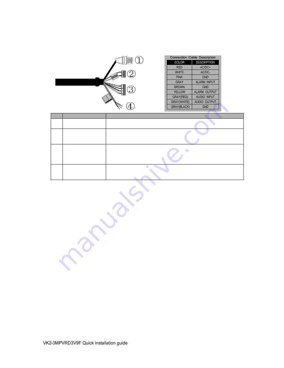
Connection Cable
NO
Wire Color
Description
1
Yellow
Ethernet, RJ-45 port compatible with 10/100Mbps having PoE
functionality. Modular Jack
2
Red:
AC24V/DC12V
White: AC24V/GND
Main Power, 3 pin terminal,
3
Pink: GND
Gray: Alarm Input
Brown: GND
Yellow: Alarm Out
Alarm Input and Output, 4pin terminal.
4
Red : Audio In
White : Audio Out
Black : GND
Audio Input and Output Cable.
Micro SD memory slot on the Board
Card Slot for Micro SD memory: Socket
“J15”
• Connecting to the RJ-45
Connect a standard RJ-45 cable to the network port of the network camera. Generally a
cross-over cable is used for directly connection to PC, while a direct cable is used for connection
to a hub.
You can also use a router featuring PoE (Power over Ethernet) to supply power to the camera.
• Connecting Alarms
AI(Alarm In) :
You can use external devices to signal the network camera to react on events. Mechanical or
electrical switches can be wired to the AI (Alarm In) and G (Ground) connectors.
G(Ground) :
Connect the ground side of the alarm input and/or alarm output to the G (Ground) connector.
Alarm Out :
The network camera can activate external devices such as buzzers or lights. Connect the device
to the AO (Alarm Out) and G (Ground) connectors.
• Connecting the Power
Connect the power of DC12V or AC24V for the network camera. Connect the po) pole to
the ‘+’ position and the negative(-) pole to the ‘-‘ position for the DC power.
Be careful not to reverse the polarity when you connect the power cable.
You can also use a router featuring PoE (Power over Ethernet) to supply power to the
camera.
The heater will operate properly only by the power source of AC 24V.
Содержание VK2-3MPVRDIR3V9F
Страница 2: ...2 ...
Страница 12: ...12 Norbain SD Ltd 210 Wharfedale Road Winnersh Triangle Wokingham RG41 5TP 01189 125 000 ...


