www.visonic.com
Page 4 of 11
D-306783 ioXpander-12x4 Module (Rev 2, 11/17)
4.
Configuration
The PowerMaster-33 E G2 can support up to 4 ioXpander-12x4 Modules for a total of 48 wired zones.
Every ioXpander-12x4 Module is connected and registered to the ioXpander-8 module using a RS-485 bus
(230000 bps).
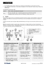
The ioXpander-12x4 has two LEDs
Green
Power - Lights continuously when powered.
Red
When the ioXpander-12x4 is connected, registered, and communicating with the
PowerMaster-33 E G2 the red LED is off. Otherwise, it blinks every second.
4.1
Inputs:
Every HW-Zone that connects to a ioXpander-12x4 Module must be enrolled in the PowerMaster-33 E G2. Each
ioXpander-12x4 Module can connect up to 12 HW Zones. For more information refer to
section 6: “Enrollment
Process.”
Configure each HW-zone wiring type setting: EOL/NO/NC based on the type of sensor wired to the zone input
(see
below).
Note:
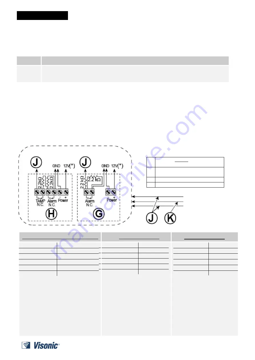
Each HW-Zone reports 3 possible states: Normal, Alarm, or Tamper. Both Line Cut and Line Short are
reported as Tamper (see below). Regarding the wired zones, the control panel classifies the events according to the
resistance it measures as shown in the tables below.
NC
–
If the Wiring Type is End of Line
If Wiring Type is NC
If Wiring Type is NO
Condition
Zone Resistance
Tamper/Short Circuit
0 ÷ 1.76 kΩ
Normal
1.77 kΩ ÷ 2.64 kΩ
Tamper
2.65 kΩ ÷ 3.52 kΩ
Alarm
3.53 kΩ ÷ 5.26Ω
Tamper/Open Circuit
5.27 kΩ ÷ oc
When there is NO ALARM - the Panel
detects 2.2K ohm between Zx and
GND.
When there is ALARM - the Panel
detects 4.4K ohm between Zx and
GND.
When there is TAMPER or cut circuit
the Panel detects
: ∞ ohm. When the
line is short circuited the panel detects
0 between Zx and GND.
Condition
Zone Resistance
Normal
0
– 1.76 kΩ
Invalid Level
1.77 kΩ – 2.64 kΩ
Invalid Level
2.65 kΩ – 3.52 kΩ
Invalid Level
3.53 kΩ – 5.26 kΩ
Alarm
5.27 kΩ –
∞
When there is NO ALARM - the
Panel detects 0 ohm (short
circuit) between Zx and GND.
When there is ALARM - the
Panel detects
: ∞ ohm (cut circuit)
between Zx and GND.
When there is TAMPER - N/A
Zone Resistance
Condition
0
– 1.76 kΩ
Alarm
1.77 kΩ – 2.64 kΩ
Invalid Level
2.65 kΩ – 3.52 kΩ
Invalid Level
3.53 kΩ – 5.26 kΩ
Invalid level
5.27 kΩ –
∞
Normal
When there is NO ALARM -
the Panel detects
: ∞ ohm (cut
circuit) between Zx and GND.
When there is ALARM - the
Panel detects: 0 ohm (short
circuit) between Zx and GND.
When there is TAMPER - N/A
G
tamper switch or
without
Detector
arming key (DEOL)
H
Detectors with tamper switch or
arming key’s tamper (DEOL)
J
Wired zones
K
GND


