ioXpander-12x4 Module
Installation Guide
www.visonic.com
Page 1 of 11
D-306783 ioXpander-12x4 Module
(Rev 2, 11/17)
E
ng
li
s
h
1.
Introduction
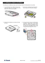
This installation guide provides the basic instructions for Visonic
’s ioXpander-12x4 Module installation scenarios. A
new addition to the PowerMaster-33 E G2 control panel, the ioXpander-12x4 Module is a wired input/output expander
that communicates with the PowerMaster-33 E G2 through the ioXpander-8 module.
ioXpander-12x4 Module Features:
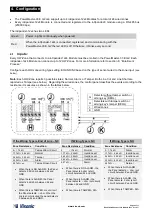
12 wired inputs that enable to connect to 12 H/W zones
4 relay outputs.
Siren output (SRN) and Strobe output (STR)
Front and back cover tamper switches for improved tamper protection
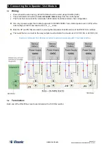
RS-485 bus to communicate with the panel
The ioXpander-12x4 Module is supported by the PowerMaster-33 E G2
only
1.1
Terminology:
Abbreviation
Definition
NO / NC
Normally Open / Normally Closed
EOL/DEOL
End of Line / Double EOL
HW-Zone
Hard wired zone
ioXpander-8
Expander and bus controller on the PowerMaster-33 E G2
PGM
Programmable Relay Output
PCB
Printed circuit board
2.
General Guidelines
1. Keep away from all heat sources.
2. Do not expose to air drafts.
3. Do not install outdoors.
4. Avoid direct sunshine.
5. Keep wiring away from power cables.
6. Mount on solid stable surfaces.
IMPORTANT:
The ioXpander-12x4 Module
MUST BE
POWERED
DOWN
while wiring the I/Os and when connecting to the RS-485 bus.
This will prevent accidental damage to the device.


