Vision Fitness R70-02 (RB87C)
Service Manual
Страница 1: ...Vision Fitness R70 02 RB87C Service Manual ...
Страница 2: ...eshooting All or Some of the Function Key Do Not Respond 15 4 4 Troubleshooting High or no resistance 16 4 5 Troubleshooting Pedals Slipping 17 4 6 Troubleshooting Knocking or Creaking Noise 17 4 7 Troubleshooting Heart Rate Function Does not Work or is Reading Incorrectly 18 4 8 Troubleshooting Seat Issues 19 CHAPTER 5 PART REPLACEMENT GUIDE 5 1 Console Replacement 20 5 2 Handlebar Replacement 21...
Страница 3: ...eplacement 36 5 17 Drive Belt Replacement 37 5 18 Idler Replacement 38 5 19 Generator Belt Replacement 39 5 20 Generator Replacement 41 5 21 Transmission Axle Set Replacement 43 5 22 Pulley Axle Set Replacement 47 5 23 Rear Stabilizer Replacement 49 5 24 Testing the Bike 50 CHAPTER 6 SOFTWARE UPGRADE PROCEDURE 6 1 Software Upgrade Instructions 51 ...
Страница 4: ...AINTENANCE SCHEDULE Item Daily Weekly Monthly Quarterly Biannual Annual Console Mounting Bolts Inspect Frame Inspect Display Console Clean Inspect Pedals Clean Inspect Seat Track Clean Handlebar Clean Inspect Handrail Handlebar Clean Inspect Belt Grooves Inspect V Belt Clean Inspect ...
Страница 5: ...erated during operation Frequency Every 3 to 4 months Procedure 1 Remove the Poly V belts 360 J6 380 J8 and check the grooves of the belt for dirt or dust and clean if any is present 2 Check the grooves in the pulley for dirt or dust and clean if any is present 3 Check the grooves in the roller pulley for dirt or dust and clean if any is present ...
Страница 6: ...6 CHAPTER 2 WIRING DIAGRAM INSTRUCTIONS 2 1 Electrical Installation ...
Страница 7: ...7 CHAPTER 2 WIRING DIAGRAM INSTRUCTIONS 2 2 Electrical Diagram ...
Страница 8: ...ING DIAGRAM INSTRUCTIONS 2 3 Wiring Diagram P01 CONSOLE WIRE 2 4 Lower Control Board Wiring Diagram J2 7 pin terminal to the console J3 3 pin terminal to the generator J4 2 pin terminal to the power resistor J3 J4 J2 ...
Страница 9: ...K1 Quick key cable for R70 JHD Console wire for S70 JAI Console wire for S60 U70 R70 JHG1 JHG2 Hand grip cable for all models Select switch Select current model by hand Select switch JQK Quick key for S70 JQK1 Quick key for R70 JHD Console digital wire for S70 JAI Console wire for S60 U R 70 JHG1 JHG2 Hand grip ...
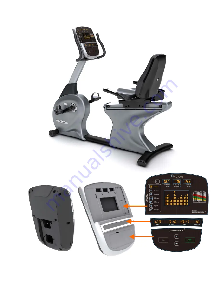
Страница 10: ...ys 3 Press the ENTER key to see the value of the function 4 To change the value of the setting use the UP and DOWN RESISTANCE keys 5 To confirm and save the value of the setting press the ENTER key 6 Press and hold the START key for 3 5 seconds to return to normal operation FIGURE A FIGURE B KEY NAME FUNCTION UP Select function or adjust value DOWN Select function or adjust value ENTER Enter the f...
Страница 11: ... all programs UNIT MILE KM MILE Set the unit to miles or kilometers MACHINE BIKE BIKE ELLIPTICAL Set machine to bike or elliptical mode ACCUMULATED TIME _ _ _ Total time the product has been used in hours ACCUMULATED DISTANCE _ _ _ Total distance the product has been used DISPLAY TEST Used by service technicians to test LED displays MACHINE TEST _ _ _ Provides a way to test heart rate and resistan...
Страница 12: ...ck the connection of power resistor or replace power resistor 0x02AB C Machine Type Error Set the Machine Type to the correct type of LCB 0x02B3 C Resistance Type Error Set the Machine Type to the correct type of LCB 0x04A0 C The LCB has no message returned to the UCB for over 3 seconds Check the console cable connections replace the LCB UCB as needed 0x0201 A LCB Battery Low Voltage Check battery...
Страница 13: ...rminals on pins 1 4 of the console cable There should be a reading of more than 5 5VDC Figure A If voltage is more than 5 5VDC replace the console If voltage is less than 5 5VDC or the new console does not resolve the issue replace the console cable 3 Open the rear shrouds then check if all the wire harnesses are connected properly to the terminals of the LCB 4 Unplug the generator cable from the ...
Страница 14: ... set your multi meter to resistance and place a terminal on pin 3 of the console cable at both the LCB and UCB There should be a resistance ohm reading Figures A B If a resistance reading is shown replace the console If the there is no resistance reading or a new console does not resolve the issue replace the console cable 3 Open the rear shrouds and check if all the wire harnesses are connected p...
Страница 15: ...s damaged 3 The UCB is damaged SOLUTION 1 Check the connections of the keypad at the UCB a Remove the console from the console mast b Remove the 6 screws holding the back of the console to the front Figure A c Inspect the keypad ribbon cable connection at the UCB Figure B d Even if the keypad ribbon cable appears to be connected correctly unplug and reseat the cable then retest 2 Replace the affec...
Страница 16: ...roperly to the LCB 3 Set your multi meter to resistance ohms and place both terminals on the power resistor wires Check the power resistor wires for resistance Figure A If the power resistor wire does not have resistance replace the power resistor 4 Unplug the generator cable from the LCB Pedal the machine and set your multi meter to AC voltage and place both terminals on pins 1 2 pins 2 3 and pin...
Страница 17: ...g is damaged replace the drive assembly 4 7 Troubleshooting Knocking or Creaking Noise KNOCKING OR CREAKING NOISE POSSIBLE CAUSES 1 The pedal is on the crank too loosely 2 The crank or axle is worn out 3 The belt tension is not high enough or the belts are too dirty SOLUTION 1 Tighten the pedal on the crank 2 Tighten the crank on the drive axle Replace the crank or axle as needed 3 Remove the cove...
Страница 18: ...f the voltage is not between 0 5 and 2 0VDC remove the 3 screws holding the HR grip together and check the connection of the HR grip wiring 2 Check continuity of the HR grip wiring a Place one terminal of a multi meter set for resistance on the HR grip wiring at the HR grip and the other terminal on the HR grip wiring at the console An ohm reading of around 1 should be expected If the reading is h...
Страница 19: ...the top of the running track Figure B c While holding pressure with the screwdriver fully tighten the nut to hold the roller bracket in place Figure C d Once the front roller brackets are tight repeat procedure with the rear roller brackets e Once the roller brackets are tightened test the seat movement for smooth travel NOTE If the seat sticks or is hard to move the pressure on the roller bracket...
Страница 20: ...able and HR connections from the defective console and remove the console Figure B FIGURE B 3 Reinstall the wire connections to the new console 4 Carefully push the wires into the console and mast until they are clear of the console mast connection and attach the console to the mast using the 4 screws removed in Step 1 5 Test the bike for function as outlined in Section 5 24 ...
Страница 21: ...rews holding the handlebar to the console mast being careful to support the handlebar Figures A B FIGURE A FIGURE B 2 Carefully remove the defective handlebar Figure C FIGURE C 3 Reverse Steps 1 2 to install a new handlebar 4 Test the bike for function as outlined in Section 5 24 ...
Страница 22: ... of the console mast Figure A and remove the 5 screws holding the console mast to the frame Figure B FIGURE A FIGURE B 4 Pull the wires out the bottom of the console mast and remove the mast Figure C FIGURE C 5 When installing a new console mast be sure to pull the console wires up through the new mast prior to installing the 5 screws into the frame 6 Test the bike for function as outlined in Sect...
Страница 23: ...CEMENT GUIDE 5 4 Cup Holder Replacement 1 Remove the 2 screws holding the cup holder to the console mast Figures A B FIGURE A FIGURE B 2 Remove the cup holder Figure C FIGURE C 3 Reverse Steps 1 2 to install a new cup holder ...
Страница 24: ...CEMENT GUIDE 5 5 Seat Pad Replacement 1 Remove the 4 screws holding the seat pad to the seat frame Figure A FIGURE A 2 Lift the seat pad away from the seat frame Figure B FIGURE B 3 Reverse Steps 1 2 to install a new seat pad ...
Страница 25: ... the plastic cover with your hand Figures A B The back cover is held on my snap clips FIGURE A FIGURE B 2 Remove the 4 screws holding the back pad onto the seat frame Figure C 3 Remove the back pad Figure D FIGURE C FIGURE D 4 Reverse Steps 1 3 to install a new back pad ...
Страница 26: ... 4 screws holding the heart rate handlebars to the seat frame Figures A B 4 Disconnect the heart rate wiring that is exposed when the heart rate handlebar is shifted Figure C 5 Remove the heart rate handlebars from the frame Figure D FIGURE A FIGURE B FIGURE C FIGURE D 6 Reverse Steps 1 5 to install a new heart rate handlebar 7 Test the bike for function as outlined in Section 5 24 ...
Страница 27: ...key grip can be split into 2 pieces Figure B FIGURE A FIGURE B 3 Disconnect the HR plate wiring quick key cable and remove the old grip Figure C 4 Reverse Steps 1 3 to install new HR grips The white wire should be on the bottom side HR plate the red wire on the upside Make sure that the end cap also gets installed Figure D FIGURE C FIGURE D 5 Test the Bike for function as outlined in Section 5 24 ...
Страница 28: ...d in Section 5 6 3 Disconnect and remove the HR handlebar as outlined in Section 5 7 4 Remove the 4 screws holding the upper seat frame to the lower seat frame Figure A FIGURE A 5 Remove the upper seat frame from the lower seat frame Figure B FIGURE B 6 Reverse Steps 1 5 to install a new seat frame 7 Test the bike for function as outlined in Section 5 24 ...
Страница 29: ...Remove the upper seat frame as outlined in Section 5 9 5 Disconnect the HR wiring that is exposed when the seat pad is removed and slide it out the hole in the frame so it does not restrict the seat movement Figures A B FIGURE A FIGURE B 6 Remove the screws holding the rear seat roller to the seat track and remove the roller Figure C 7 Remove the 2 screws holding the rear end cap onto the seat tra...
Страница 30: ... Continued 8 Remove the end cap Figure E 9 Pull up the seat adjustment handle bar and push the lower seat frame off from the seat track Figure F FIGURE E FIGURE F 10 Reverse Steps 1 9 to install a new lower seat frame 11 Test the bike for function as outlined in Section 5 24 ...
Страница 31: ...t 1 Remove the 2 screws holding the seat adjustment handle to the seat frame Figure A B FIGURE A FIGURE B 2 Remove the seat adjustment handle Figure B FIGURE B 3 Reverse Steps 1 2 to install a new seat adjustment handle 4 Test the bike for function as outlined in Section 5 24 ...
Страница 32: ...g the right side shroud to the frame and left shroud and remove it Figure A 2 Remove the 5 screws holding the left side shroud to the frame and remove it Figure B FIGURE A FIGURE B 3 Figure C shows the bike with both rear shrouds removed FIGURE C 4 Reverse Steps 1 2 to install a new rear shroud ...
Страница 33: ...Remove the 2 screws holding the lower board to the frame Figure B and remove the lower control board FIGURE A FIGURE B 4 Reverse Steps 1 3 to install a new lower board Figure C shows the connections at the board FIGURE C 5 Test the bike for function as outlined in Section 5 24 J2 7 pin terminal to the console J3 3 pin terminal to the generator J4 2 pin terminal to the power resistor J3 J4 J2 ...
Страница 34: ...l wrench to remove the pedal from the crank Figure A NOTE For the right side pedal the threads are normal For the left side pedal the threads are reversed the pedal turns off counterclockwise FIGURE A 2 Remove the pedal Figure B FIGURE B 3 Reverse Steps 1 2 to install a new pedal ...
Страница 35: ...ifferent on the tool 2 Remove the crank arm cover Figure B Figure A Figure B 3 Attach the 1 side of the tool into the crank and use a wrench to remove the nut from the crank Figure C 4 Thread the 2 side of tool into the crank Then turn it at least 7 full revolutions until it is close into the crank Figure D FIGURE C FIGURE D 5 Turn the 1 side of the tool to pull off the crank Figures E F FIGURE E ...
Страница 36: ...ng the right side front shroud to the frame and the left shroud and remove it Figure A NOTE You will need to angle the shrouds so that the crank passes through the hole in the shroud FIGURE A 3 Remove the 4 screws holding the left side front shroud to the frame and remove it Figure B FIGURE B 4 Reverse Steps 1 3 to install a new front shroud ...
Страница 37: ...alk the belt off the pulley Figure A 3 Remove the drive belt Figure B FIGURE A FIGURE B 4 Reverse Steps 1 3 to install a new drive belt NOTE Be sure to re attach the tension spring Figure C If more tension is needed on the drive belt multiple holes are available for the lower spring attachment Figure C FIGURE C 5 Test the bike for function as outlined in Section 5 24 ...
Страница 38: ...dler set is attached to the frame with one bolt and a nut Figures A B FIGURE A FIGURE B 3 Remove the tension spring Figure C 4 Remove the idler set Figure D FIGURE C FIGURE D 5 Reverse Steps 1 4 to install a new Idler set NOTE Torque the bolt removed in Step 2 to 30 N m 6 Test the bike for function as outlined in Section 5 24 ...
Страница 39: ... wire connector of the generator and unplug the generator wire from the LCB Figure A 3 Remove the nuts holding the generator to the frame Figure B FIGURE A FIGURE B 4 Remove the nuts putting tension on the generator belt Figure C 5 Remove the small screw at the right side of frame that keeps the generator from spinning freely Figure D FIGURE C FIGURE D ...
Страница 40: ...re E 7 Pull the generator out of the frame towards the front of the unit and remove the generator belt Figure F FIGURE E FIGURE F 8 Reverse Steps 1 7 to install a new generator belt NOTE Be sure to re tension the new generator belt to 80 ft lbs of torque 9 Test the bike for function as outlined in Section 5 24 ...
Страница 41: ... connector of the generator and unplug the generator wire from the LCB Figure A 3 Remove the nuts holding the generator to the frame Figure B FIGURE A FIGURE B 4 Remove the nuts putting tension on the generator belt Figure C 5 Remove the small screw at the right side of frame that keeps the generator from spinning freely Figure D FIGURE C FIGURE D ...
Страница 42: ...re E 7 Pull the generator out of the frame towards the front of the unit and remove the generator belt Figure F FIGURE E FIGURE F 8 Reverse Steps 1 7 to install a new generator NOTE Be sure to re tension the new generator belt to 80 ft lbs of torque 9 Test the bike for function as outlined in Section 5 24 ...
Страница 43: ...in Section 5 16 2 Remove the drive belt from the pulley by hand Figure A 3 Remove the C clip holding the bearing in place on the left side of the frame Figures B C FIGURE A FIGURE B 4 Install two nuts onto the drive axle and turn the nuts until the heads are close to the drive axle Figure D FIGURE C FIGURE D ...
Страница 44: ...le until the drive axle assembly is loose in the frame and remove it Figures E F FIGURE E FIGURE F 6 Use a mallet with a punch to hit the remained bearing until it is removed from frame Figure G H NOTE The bearings on the drive axle cannot be re used after removal of the drive axle assembly FIGURE G FIGURE H ...
Страница 45: ...ing housing section of the frame Figure I J FIGURE I FIGURE J 8 Daub the left side of the bearing housing section of the frame with a fixative Red Loctite 603 is recommended Figure K 9 Mount the bearing into the housing and wait about 30 minutes until they are adhered Figure L FIGURE K FIGURE L ...
Страница 46: ... the drive axle assembly until it is close to the frame Figure N NOTE Be sure to install the nuts from Step 5 onto the new drive axle assembly to protect the axle prior to completing this step FIGURE M FIGURE N 12 Install the bearing into the left side of the frame 13 Reverse Steps 1 3 to complete installation of a new drive axle set 14 Test the bike for function as outlined in Section 5 24 ...
Страница 47: ...in Section 5 16 2 Remove the drive belt from the pulley by hand Figure A 3 Remove the tension spring Figure B FIGURE A FIGURE B 4 Remove the generator belt from the pulley by hand Figure C 5 Remove the screw holding the bearing to the pulley axle on the right side of the frame Figure D FIGURE C FIGURE D ...
Страница 48: ...9 Install a screw into the secondary axle and turn the screw until the head is close to the secondary axle Use a mallet to hit the screw until the pulley axle assembly is loose in the frame and remove it Figure H FIGURE G FIGURE H 10 Reverse Steps 1 9 to install a new pulley axle set NOTE The bearings on the pulley axle cannot be re used after removal of the pulley axle assembly NOTE Clean the bea...
Страница 49: ... 23 Rear Stabilizer Replacement 1 Lean the bike to one side and remove the 4 screws holding the rear stabilizer to the frame Figure A FIGURE A 2 Remove the rear stabilizer Figure B FIGURE B 3 Reverse Steps 1 2 to install a rear stabilizer ...
Страница 50: ...e is not set for Bike change to Bike using the UP or DOWN RESISTANCE keys and press STOP to save e Press and hold the STOP key for 3 5 seconds to return to normal function 2 Without hitting start or entering any program modes sit on the bike and hold the handlebars while pedaling to simulate exercising While moving listen for any odd noises or squeaks 3 After stopping movement press the green GO k...
Страница 51: ...ARE UPGRADE PROCEDURE 6 1 Software Upgrade Instructions A Service Tools Accessories 1 MSP FET430 Gang Programmer 2 Parts number MT00L 039 3 Software A 14 PIN B POWER SUPPLY SPECIFICATION 8 15V 300MA MSP FET430 TOOLS A B ...
Страница 52: ...up is ADT430 The MSP430 FLASH Gang Programmer GUI is displayed on the screen as shown in Figure B FIGURE B The status message in the GUI displays the message MSP GANG430 Gang Programmer connected If this message is not displayed check the COM Port selection in the communication settings of PC and the MSP GANG430 connections 3 Follow sequence 3 1 3 8 to setup the parameter as shown in Figure C 3 1 ...
Страница 53: ... 3 5 Use the Load Image button to download the console software file to the MSP GANG430 as shown in Figure A 3 6 Select the supply voltage for the console from MSP GANG430 3 7 Select the options in Main Process as required 3 8 When you install the first console please connect MSP GANG430 with computer Click on the Start button in the Main Process section to start the console install The progress a...
Страница 54: ...e install passes the OK green LED will light as shown in Figure F FIGURE D FIGURE E FIGURE F 5 Install the console onto frame Then pedal the machine to provide power for the console Enter into Engineering Mode to confirm if the software has been installed upgraded and confirm if the machine type is right 6 Test the bike for function as outlined in Section 5 24 1 Press START button 2 The MODE LED w...