AXS-10
Single-Door Access Control System – Installation Guide
Page 5 of 8
DE6270_V10
To assign a master key:
•
Press the “Mode” button.
•
Enter installer password. The green “ADD” LED starts flashing.
•
Press “MODE” a few times until the display shows: ”S0”. The
system is ready to read the key. Present a tag or card to the
top right corner of the controller (internal proximity reader).
•
Once a key is presented, it will replace the current master key.
Hold the new key until the “SPECIAL” LED stops flashing.
•
To revert to normal operation, wait 10 seconds until the AXS-
10 automatically exits the programming menu.
•
To program the master magnetic stripe card, perform steps A,
B and C. When you are instructed to present a tag or a card,
present the desired magnetic stripe card to the magnetic stripe
reader RDC-3 or RDC-3MP.
5.3 Erasing ALL User Keys
IMPORTANT: A user master key should be assigned before
erasing user keys.
•
To select the ERASE ALL mode press the “MODE” button.
•
Enter installer password. The green “ADD” LED starts flashing.
•
Press the “MODE” button a few times until the “SPECIAL” LED
lights and the display shows “Er”.
•
Present the master key to the top right corner of the controller.
•
Remove the key and wait until the display blanks out.
•
To erase all magnetic stripe cards, perform steps A, B and C.
When you are instructed to present the master key, present the
magnetic stripe card to a magnetic stripe reader RDC-3 or RDC-
3MP.
Note: The ERASE ALL function does NOT erase the master key.
•
Wait 10 seconds until the AXS-10 automatically exits the
programming menu.
5.4 Setting the Door Unlock Duration
The system default unlock duration is 5 seconds. The time can be
set between 1 to 99 seconds.
Note: In Toggle mode, the unlock duration is unlimited (until a
valid tag is presented).
Setting Door Unlock Period:
•
Press the “MODE” button.
•
Enter the installer password. The green “ADD” LED will start
flashing.
•
Press the “MODE” button a few times until the “SPECIAL” LED
lights and the display shows “UL”.
•
Press F2 (tens) and F3 (units) to set the unlock time in
seconds. For example, for 35 seconds press “10” three times
and “1” five times.
•
The display will show the number of seconds.
•
To save the unlock time and return to normal operation,
present the master key to the internal reader.
•
You may press “MODE” at any time to continue without saving
the new unlock duration.
5.5 Entering/Exiting Toggle Mode
To turn the AXS-10 into Toggle mode:
Setting the Unlock Duration (see par. 5.4) to 100 seconds turns
the AXS-10 into
Toggle
mode. If the unlock time setting is less
then 100 second, the AXS-10 is in regular mode.
To turn the AXS-10 from Toggle mode into Regular mode:
Set the unlock duration to any number other than "100". Then exit
the "Unlock Duration" mode.
To turn the AXS-10 into Toggle mode by using master tag:
•
While the system is in idle mode present the master tag for 5
seconds to the RDR-3 reader or present the master magnetic
stripe card to the magnetic stripe reader RDC-3 or RDC-3MP.
•
The LED will change to green (the lock is unlocked and the
AXS-10 turns into Toggle mode).
•
Presenting any valid non-master key will turn the relay to lock
position.
To turn the AXS-10 from Toggle mode to regular mode by
using the master key:
While the system is in idle mode, present the master tag card for
5 seconds or present the master magnetic stripe card. The LED
will blink red, which means that the AXS-10 is in regular mode
.
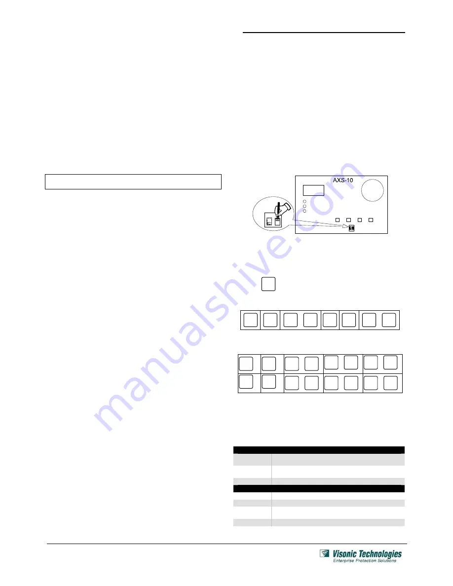
5.6 Resetting the Installer's Password
•
Gain access to the DIP switches, as shown in figure 3 (steps
1-4) and figure 5 (steps 1-2).
•
Move the rightmost switch up (password reset).
A password consists of six button keying sequence. Each press
involves either pressing a single button or a combination of two
buttons.
Press
MODE
display will show ---.
Press the following sequence:
MODE
F1
100
MODE
+
F1
100
F2
10
F3
1
F2
10
+
F3
1
•
The display should show IP (Installer Password).
•
Enter the new installer password (6 button presses). The
following table shows the possible combinations:
פ
MODE
F1
100
MODE
+
F1
100
MODE
+
F2
10
MODE
+
F3
1
F2
10
F3
1
F1
100
+
F2
10
F1
100
+
F3
1
F2
10
+
F3
1
•
Move the rightmost switch down (off).
•
Replace the PCB and remount top cover.
5.7 Setting User Password
To set the user password, see section 2.9 in AXS-10 User Guide
Ordering Details
AXS-10
S
YSTEMS
3-6270-0
AXS-10, Single door, 300-key memory controller
(readers sold separately)
3-6271-0
AXS-10 KIT, Single door, 300-key memory controller
with RDR-3 proximity reader
3-6271-2
AXS-10 Pro, Single door cont proximity reader, 300 users
C
OMPATIBLE
A
CCESS
C
ONTROL
R
EADERS
3-6302-0
RDR-3, Proximity Reader (5 - 10 cm/2 – 4 inch read range)
3-6295-0
RDC-3, Indoor, Plastic, Magnetic Strip Reader
3-6308-0
RDM-3, Proximity reader (4 - 8 cm/1.6 – 3.1 inch read range),
Mullion-design
3-6297-1
RDC-3MP, Metal, Outdoor, Anti-vandal Magnetic Stripe Reader


