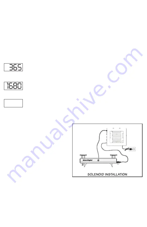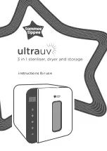
Possible causes for low UV alarm conditions:
a) The UV lamps have perhaps reached a level whereby they can no longer adequately
provide a sufficient level of disinfection due to age (> 9000 hours). The lamps
should be replaced with new lamps from the manufacturer of the same size and
type.
b) The quartz sleeves and/or the sensor window have become stained or dirty.
Mineral deposits or sediment in the water that was not detected during the original
water analysis may be the cause for this (refer to page 9 for cleaning instructions).
c) Intermittent voltage drop in the line power supply reducing the lamp output. The
lamp will return to normal when the power is restored to full voltage.
Note: the
monitoring system will not operate during power failures.
d) The quality of the influent water has changed and is no longer within the
acceptable operational range of the UV system. Perform a water analysis to
determine the exact constituents and concentration levels.
e) The UV sensor is not installed correctly (see page
10
).
2. Lamp life remaining (days):
To obtain this reading, press the push-button SWITCH a single time and follow the
steps as outlined on page
11
, regarding the operation of this feature.
3. Total days of operation:
To obtain this reading, press the push-button SWITCH two times in succession and
follow steps as outline on page
11
, regarding the operation of this feature.
4. Lamp failure (blank screen):
Please refer to page
10
for explanation of this feature.
Note:
On the Hi-Flo Monitored systems, the audible tone provided for lamp failure is
a continuous alarm, rather than the intermittent (1 second on, 1 second off)
condition on the basic Hi-Flo systems.
5. Solenoid Output:
Working in conjunction with the UV intensity
monitor, the Hi-Flo Monitored controller
provides a powered (line voltage) IEC
solenoid output connector. (Note: this is
not a dry contact) This solenoid output is
protected with a replaceable 2 amp isolated
fuse. Connection from this output to the
solenoid can be done using the IEC solenoid
power cable PN 260184-R. When the UV
intensity monitor senses that the water is
not adequately being treated and drops to
49% UV intensity or below, the internal relay
is opened thereby stopping AC power flowing to the normally closed solenoid valve.
The valve will remain closed (no power) until the UV level rises above
49%, at which time the solenoid will open, allowing for water to pass through.
(To temporarily enable the operation of this solenoid output for up to 12 hours,
please refer to the instructions outlined on page 12 of this manual).
13
SOLENOID TO BE
INSTALLED ON INLET
OR OUTLET
INLET/OUTLET
OPTIONAL
DRAIN COCK
INLET/OUTLET
STERILIGHT
HI-FLO
CUTOMER SUPPLIED
GFCI CIRCUIT
TO MATCH VOLTAGE
HF


