


This document is the pr
operty o
f VINSER
VICE and mus
t no
t be r
epr
oduc
ed or tr
ansf
err
ed t
o thir
d parties without permis
sion.
2
REV
. 17/09/19
This document is the pr
operty o
f VINSER
VICE and mus
t no
t be r
epr
oduc
ed or tr
ansf
err
ed t
o thir
d parties without permis
sion.
3
REV
. 17/09/19
QUICK GUIDE
QUICK GUIDE
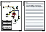
The probe positioned inside the water tank reads the ice bank thickness and regulates
the compressor working in order to keep the ice bank constant during running.
OPTIONAL: mechanical thermostat (TM)
The mechanical thermostat can be adjusted by means of a flat-head screwdriver. The ther
-
mostat needs to be positioned, according to the operating conditions:
Hydraulic connections
The equipment is supplied with ready hydraulic connections. It contains steel cooling coils
ready to be connected to the inlet and outlet cooling beverage tubes.
Appliance start-up
The quick chiller operation is completely automatic and does not require any particular
operation by the operator. Anyway, first of all make sure that there are no leaks present in
the system circuits, including the inlet and outlet beverage circuits, before start-up. This
check must be carried out periodically, as the appliance can be kept running permanently.
After making sure that all previously described conditions are present and necessary ope-
rations duly carried out (electrical connections, hydraulic circuit connection, tank filling,
etc...), power on the machine by turning the main bipolar switch (IG); check that the
built-in warning light goes on. • After powering on, the fan (M), the stirrer pump (F) and
the compressor (H) start working. After about 3-6 hours (according to the model and the
installation conditions), the compressor and the fan stop, as a suitably-thick ice bank has
formed. Anyway, the stirrer keeps on running and moving the tank and recirculation water
in the cooling coil, to facilitate the heat exchange (cooling of beverages in the cooling coil
and in the dispenser column).
The formation of the ice bank around the evaporator (O) takes place gradually and starts
immediately after the equipment is started up.
The tank-dipped probe (G) checks the formation of the ice bank and controls the cooling
system working by means of an electronic regulator (TE), in order to keep the ice bank
constant during the appliance operation.
On request a mechanical thermostat (TM) and a transformer (TR) for additional food com
-
ponents can be installed.
• Winter operation:
the notch visible on the adjusting pin is posi-
tioned on a value between 1 and 6 according to the temperature
of the installation environment. The lower position (1) is recom-
mended for very low temperatures of the installation site (3°
- 4°C). the following positions are to be selected according to
the increase in temperature of the installation environment: any
10°C of temperature increase require the selection of a higher
position.
• Summer operation:
adjust the thermostat so as to bring the thi-
ckness of the ice bank desired (between 20 and 40 mm) around
the evaporator.
MAINTENANCE
Ordinary maintenance
CAUTION: ALWAYS TURN THE APPLIANCE OFF AND DISCONNECT THE POWER CABLE
FROM THE ELECTRICITY OUTLET BEFORE OPENING THE INSPECTION PANEL OR AC-
CESSING INSIDE THE CASING ANYWAY.
THE CABLE MUST BE LEFT DISCONNECTED UNTIL ALL OPENINGS AND PANELS HAVE
BEEN REPOSITIONED IN THEIR ORIGINAL POSITION AND THE SCREW-FASTENED PAR-
TS RE-TIGHTENED. THE APPLIANCE MUST NOT BE CLEANED WITH A WATER JET OR
OTHER LIQUID.
Ordinary maintenance can be carried out by common personnel in strict compliance with
the instructions given below.
• Daily: check for leaks in the various system circuits.
•
Every six months: clean the condenser (L) blades with a brush and/or a soft brush
and/or a compressed air jet. CAUTION: Wear protective leather gloves: the condenser
blade edges are sharp and may cut your hands. Do not bend the blades.
•
Every month, or as needed, sanitize or wash the cooling coils (A) through which the
beverages flow. Wash and rinse them with plenty of drinkable water. Only use deter
-
gents suitable for food industry according to the supplier’s instructions.
•
Every month: check that the “overflow” discharge opening is not clogged by ice, dirt
or residues of any kind.
•
Every month: clean the machine, remove any residues (including filaments, paper frag
-
ments or other materials) which may prevent the normal working of the system or of
the various motors, in order to avoid overheating.
Extraordinary Maintenance
Extraordinary maintenance must be performed by specialized personnel exclusively.
•
Every year: change the tank water according to the procedure reported below.
Change of the tank water
This procedure is to be carried out any time there is a need to change the tank water.
1.
Turn off and disconnect the machine power cable from the electric socket
2.
Remove the upper covers
3. Wait until the ice bank has fully thawed
4.
Empty the tank through the draining pipe located on the side of the machine (if any)
or drain it into a suitable discharge system
5. Fill the tank with clean water up to the level indicated on the tank edge
6.
Remove the upper covers
7.
Reconnect the power cable and restart the appliance
ICE
BANK
STOP
3
4
5
2
6
1
E
F
G
Q
O
A
TR
B
M
L
D
H
N
R
C


