


16
KLYS
Contents: Page
Product characteristics ....................................................................................................................................................................................................16
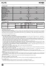
Technical data..................................................................................................................................................................................................................17
Limitations of use.............................................................................................................................................................................................................17
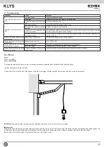
Standard system set-up...................................................................................................................................................................................................17
Mechanical installation on sectional door ........................................................................................................................................................................17
Mechanical installation on up-and-over door ...................................................................................................................................................................17
Control unit description ....................................................................................................................................................................................................18
Connection to the mains electricity ..................................................................................................................................................................................18
Accessory connections ....................................................................................................................................................................................................18
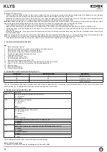
Dip-switch functions.........................................................................................................................................................................................................19
Trimmer function ..............................................................................................................................................................................................................19
Button functions ...............................................................................................................................................................................................................19
Travel programming ........................................................................................................................................................................................................19
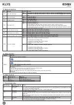
Remote control programming ..........................................................................................................................................................................................20
Courtesy light...................................................................................................................................................................................................................20
Emergency battery ..........................................................................................................................................................................................................20
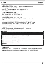
Troubleshooting ...............................................................................................................................................................................................................21
User manual
....................................................................................................................................................................................................................21
EC declaration of conformity ...........................................................................................................................................................................................22
The following safety information is an integral and essential part of the product and must be supplied to the user.
Read it carefully as it provides important guidelines regarding installation, use and maintenance. Always store this module carefully and transfer it to any
subsequent users of the system. Incorrect installation or improper use of the product may constitute a serious hazard.
SAFETY INSTRUCTIONS FOR INSTALLERS
- Carefully read the instructions on this leaflet: they give important information on the safety, use and maintenance of the installation.
- After removing the packing, check the integrity of the set. Packing components (plastic bags, expanded polystyrene etc.) are dangerous for children. In-
stallation must be carried out according to national safety regulations.
- Before connecting the set, ensure that the data on the label correspond to those of the mains.
- This apparatus must only be used for the purpose for which it was expressly designed, e.g. for automation systems for gates, garage doors and road bar-
riers. Any other use may be dangerous. The manufacturer is not responsible for damage caused by improper, erroneous or irrational use.
- Before cleaning or maintenance, disconnect the set.
- In the event of faults and/or malfunctions, disconnect from the power supply immediately by means of the switch and do not tamper with the apparatus.
- For repairs apply only to the technical assistance centre authorized by the manufacturer.
- Safety may be compromised if these instructions are disregarded.
- Installers must ensure that manuals with the above instructions are left on connected units after installation, for users’ information.
- All items must only be used for the purposes designed.
- WARNING:
to prevent injury, this apparatus must be securely attached to the wall in accordance with the installation instructions.
- This leaflet must always be enclosed with the equipment.
Directive 2002/96/EC (WEEE)
The crossed-out wheelie bin symbol marked on the product indicates that at the end of its useful life, the product must be handled separately from
household refuse and must therefore be assigned to a differentiated collection centre for electrical and electronic equipment or returned to the dealer
upon purchase of a new, equivalent item of equipment.
The user is responsible for assigning the equipment, at the end of its life, to the appropriate collection facilities.
Suitable differentiated collection, for the purpose of subsequent recycling of decommissioned equipment and environmentally compatible treatment and di-
sposal, helps prevent potential negative effects on health and the environment and promotes the recycling of the materials of which the product is made. For
further details regarding the collection systems available, contact your local waste disposal service or the shop from which the equipment was purchased.
Risks connected to substances considered as
dangerous (WEEE).
According to the WEEE Directive, substances since long usually used on electric and electronic appliances are considered dangerous for people and the envi-
ronment. The adequate differentiated collection for the subsequent dispatch of the appliance for the recycling, treatment and dismantling (compatible with the
environment) help to avoid possible negative effects on the environment and health and promote the recycling of material with which the product is compound.
Product is according to EC Directive 2004/108/EC and following norms.
1. Product characteristics:
24 Vdc drive operator for residential sectional doors up to 9 m
2
(ENM1) and condominium doors up to 12 m
2
(ENM2). It can also be installed on up-and-over
doors with counterweights using the specific adapter boom:
- electronic card with switching power, battery charger, 433 MHz receiver and built-in LED courtesy light
- memory for 10 2-channel remote controls
- optional emergency batteries that can be housed in the operator
- minimum height: 119 mm including track
- can be coupled with belt tracks for doors height 2.5 and 3.5 m supplied with brackets for assembly away from the ceiling.
EN
Содержание ELVOX KLYS ENM1
Страница 3: ...3 KLYS 110mm 10mm max 38cm 60cm 7 5 6 8 9 10 a b a b Motor I EN...
Страница 4: ...4 KLYS 45 11 12 14 13 15 16 I EN...
Страница 5: ...5 KLYS 18 17 1 cm 19 a b c 20 mm 5 mm max 50 mm d f e A 20 a b c a b c d e f d f e A I EN a b c 3 mm...
Страница 6: ...6 KLYS 100 mm max 10 20 mm 8 m S 20 30 mm 8 mm 21 22 a b 23 a b I EN...
Страница 7: ...7 KLYS 24 25 N L 1 11 2 3 4 13 5 12 8 9 6 10 7 14 51 62 61 0 1 10 5 26 27 115 230 V ac I EN...
Страница 23: ...23 KLYS...


