9
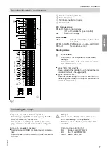
VFS/US
0-10V
PWM1
?
22
V40
S10
20
19
S9
18
17
0-10V
PWM2
?
24
0-10V
PWM1
?
22
0-10V
PWM3
?
26
0-10V
PWM4
?
28
?
30
32
31
+VBus-
2
1
S1
4
3
S2
6
5
S3
8
7
S4
10
9
S5
12
11
S6
14
13
S7
16
15
S8
Temp. sensor
Flow rotor
1
1
1
1
A
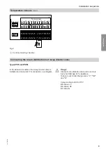
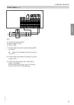
Fig.4
A
Control unit wiring chamber
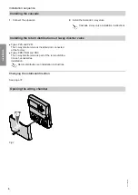
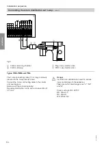
Connecting the return distribution set 3-way diverter valve
Types PZS and PZM
In the delivered condition, the 3-way diverter valve is
installed and connected. For connection, see diagram.
Danger
Incorrect core allocation can result in serious
injury and damage to the appliance.
Take care not to interchange cores "L'", "R2"
and "N".
Colour coding to IEC 60 757:
BN Brown: L'
BK Black: R2
BU Blue: N
Installation sequence
Temperature sensors
(cont.)
5517 095 GB
Installation
Содержание VITOTRANS 353
Страница 50: ...50 5517 095 GB ...
Страница 51: ...51 5517 095 GB ...


