background image

23

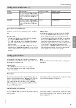
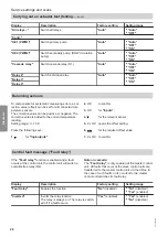
Display

Description

Factory setting

Setting range

"

Δ

T ON"

Only for 

"Type"


"Differential"

:

Start temperature differential for
return stratification 

"Differen-

tial"

10.0 K

0.5 to 20.0 K

"

Δ

T OFF"

Only for 

"Type"


"Differential"

:

Stop temperature differential for
return stratification 

"Differen-

tial"

6.0 K

0.5 to 20.0 K

Type of return stratification

2 function modes can be selected for return stratifica-
tion.

"Thermostat"

:

Changeover between 2 cylinder areas or cylinders
by using the 

"DHWcircRT sensor"

If 

"T ON"

 is exceeded at the 

"DHWcircRT sensor"

,

the return is fed into the upper cylinder area or the
hotter cylinder.

If the limit temperature 

"T ON" - "Hysteres."

 is not

reached at the 

"DHWcircRT sensor"

 (S4 or S6), the

return is fed into the lower cylinder area or the cooler
cylinder.

"Differential"

:

Changeover between 2 cylinder areas or cylinders
by using the 

"DHWcircRT sensor"

 and an addi-

tional cylinder temperature sensor (accessories)

If the temperature differential 

"

Δ

T ON"

 is exceeded

between the 

"DHWcircRT sensor"

 (S4 or S6) and

the cylinder temperature sensor (S5), the return is
fed into the upper cylinder area or the hotter cylinder.

If the 

"

Δ

T OFF"

 temperature differential is not

reached between 

"DHWcircRT sensor"

 and the cyl-

inder temperature sensor, the return is fed into the
lower cylinder area or the cooler cylinder.

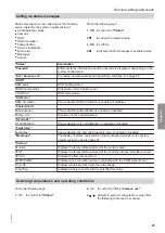
Setting pasteurisation

Pasteurisation prevents the formation of legionella in
the DHW pipes and DHW circulation pipes of the heat
exchanger on the DHW side.

Requirements:

The 

"DHW circ."

 function must be enabled.

The heat generator must make a sufficient heat
amount available.

Note

DHW circulation remains continuously on during pas-
teurisation.

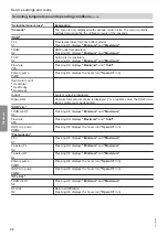
Procedure

The primary pump speed is regulated during pasteuri-
sation so that the adjustable 

"T pasteu. set"

 tempera-

ture is maintained at the relevant 

"TDHW sensor"

(S2). Pasteurisation is successful if the 

"T pasteu.

set"

 temperature 

 5 K is exceeded at KS4 or S6 for

the period 

"Pasteu. dur."

.

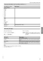
Once pasteurisation is complete, the results are shown
in the status messages; see page 25.

Pasteurisation in cascades

The set 

"Pasteu. dur."

 is split evenly between the cas-

cade modules.

Once pasteurisation is complete, the results are shown
in the status messages of the relevant cascade control
unit; see page 25.

Commissioning

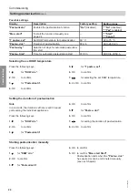
Setting return stratification

 (cont.)

5517 095 GB

Commissioning


Содержание VITOTRANS 353

Страница 1: ...Installation and service instructions for contractors VIESMANN Vitotrans 353 Control unit For applicability see the last page VITOTRANS 353 5517 095 GB 2 2015 Please keep safe ...

Страница 2: ...VDE and locally applicable standards a ÖNORM EN and ÖVE c SEV SUVA SVTI SWKI and SVGW Working on the system Isolate the system from the power supply e g by removing the separate fuse or by means of a mains isolator and check that it is no longer live Safeguard the system against reconnection Please note Electronic assemblies can be damaged by elec trostatic discharge Prior to commencing work touch...

Страница 3: ...summer wintertime changeover 17 Setting the time and date 17 Setting the display 18 Setting DHW 18 Starting the comfort function manually 19 Starting the comfort function automatically 20 Settings for the comfort function 20 Setting DHW circulation 20 Function modes of DHW circulation 21 Manual balancing of the DHW circulation pump 22 Setting return stratification 22 Type of return stratification ...

Страница 4: ...bling emergency mode 37 Changing the rotational direction of the 3 way diverter valve 37 Replacing the MCB fuse 39 6 System example System example individual appliance 40 Designations in the system example 40 Installation scheme 41 System example cascade 42 Designations in the system example 42 Installation scheme 43 7 Specification 44 8 Overview of menu struc ture Menu structure individual contro...

Страница 5: ...ese instructions The appliance may only be installed and operated in sealed unvented systems to EN 12 828 DIN 1988 with due attention paid to the associated installation serv ice and operating instructions Heating water buffer cylinders are intended exclusively for fill water of pota ble water quality Intended use presupposes that a fixed installation in conjunction with permissible system specifi...

Страница 6: ...ZM The 3 way diverter valve is installed and connected at the factory Types PBS PBM and PBL The 3 way diverter valve is part of the return distribu tion set accessories Installation Return distribution set installation instructions Changing the rotational direction See page 37 Opening the wiring chamber 1 Fig 1 Installation sequence Installing the cascade 5517 095 GB Installation ...

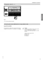
Страница 7: ...pes PBS PBM and PBL Route cables to the outside through the rear thermal insulation cut out in the upper part Types PZS and PZM Route the cables through the hole for the return on the heating water side in the support panel and the rear thermal insulation Connecting the pumps Pump to be connected individual appliance Secondary pump DHW circulation pump from the DHW circulation set accessories Conn...

Страница 8: ...stratification optional Sensors to be connected cascade S5 Additional cylinder temperature sensor for tem perature dependent return stratification optional S6 DHW circulation return sensor optional Installation Installation instructions for the heating water buf fer cylinder or sensor manufacturer s instructions Connection In accordance with system example and diagram Extension with recommended co...

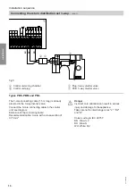
Страница 9: ...onnecting the return distribution set 3 way diverter valve Types PZS and PZM In the delivered condition the 3 way diverter valve is installed and connected For connection see diagram Danger Incorrect core allocation can result in serious injury and damage to the appliance Take care not to interchange cores L R2 and N Colour coding to IEC 60 757 BN Brown L BK Black R2 BU Blue N Installation sequenc...

Страница 10: ...ve Connect the 3 core connecting cable in the control unit see diagram Extension of the connecting cable Recommended cable 3 core with a cross section of 0 75 mm2 Danger Incorrect core allocation can result in serious injury and damage to the appliance Take care not to interchange cores L R2 and N Colour coding to IEC 60 757 BN Brown L BU Blue N WH White R2 Installation sequence Connecting the ret...

Страница 11: ... M 1 BN BU GNYE Fig 7 Danger Incorrect core allocation can result in serious injury and damage to the appliance Take care not to interchange cores R1 and N Colour coding to IEC 60 757 BN Brown R1 BU Blue N GNYE Green yellow PE Installation sequence Connecting the return distribution set 3 way cont 5517 095 GB Installation ...

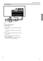
Страница 12: ...supply and implement all safety measures e g RCD circuit in accordance with IEC 60364 4 41 the connection requirements of your local power supply utility and VDE or national regula tions Protect the control unit power cable with an appropri ate fuse Disconnect the system by means of a device that simultaneously separates all non earthed conductors with at least 3 mm contact separation We also reco...

Страница 13: ... filled and vented Vitotrans 353 installation and service instruc tions 2 Check whether all electrical connections have been correctly made 3 Connect the power cable in the control unit as shown in the diagram Recommended power cable 3 core with a cross section of 0 75 mm2 with standard plug Installation sequence Power supply cont 5517 095 GB Installation ...

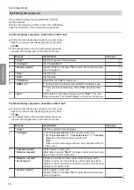
Страница 14: ... is shown on the screen Commissioning sequence cascade control unit During the commissioning sequence you can jump back to a previous commissioning step at any time with The settings made in the commissioning sequence can also be changed later in the relevant menus Display Explanation See page 1 Lang Set the required menu language 17 2 Cont type Set Cascade master at the master control unit Set Ca...

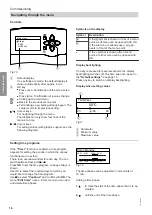
Страница 15: ... commissioning menu in all control units with Save The settings are saved The default display is shown on the screen Special features of the cascade control units Some menu points are only available to the master control unit They are not shown on the screens of the slave control units The DHW menu settings have to be made in the master control unit They apply to all subscribers of the cascade The...

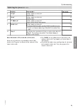
Страница 16: ... is pressed for several seconds the display backlighting switches off The time span can be set in the Default settings see page 18 Press any key to switch on display backlighting Display when setting values A B C T DHW set 50 C 20 55 60 Fig 11 A Parameter B Minimum value C Maximum value Setting time programs If the Timer function is enabled a time program appears for setting the periods in which t...

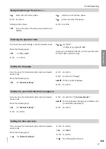
Страница 17: ...d master control units Press the following keys 1 for Default settings 2 OK to confirm 3 OK to confirm for Lang 4 for the required language 5 OK to confirm Setting the summer wintertime changeover Can only be set for individual control units and master control units Press the following keys 1 for Default settings 2 OK to confirm 3 OK to confirm for xSummer winter 4 for Yes automatic changeover ena...

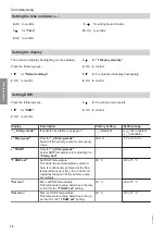
Страница 18: ...led X Yes enabled disabled Emerg spd Only for X Emerg mode Speed of the primary pump for emergency mode 30 0 1 5 to 100 0 TDHW Only for X Emerg mode Actual DHW temperature for adjusting the Emerg spd T DHW set Set DHW temperature To ensure the set temperature selected here is continuously achieved at the flow temperature sensor S2 the control unit regulates the speed of the primary pump accordingl...

Страница 19: ...Blocking time for the comfort function after it was active 10 min 0 to 60 min Timer Only with Comfort ON Setting a time program to automatically start the comfort function TDHW set modu la If the set DHW temperature TDHW set cannot be achieved at the flow temperature sensor S2 the TDHW set is set back dynamically Setback occurs for T FL T DHW set ΔT modulat T FL actual DHW temperature T DHW set mo...

Страница 20: ...If DHW circulation is available Press the following keys 1 for DHW circ 2 OK to confirm Display Description Factory setting Setting range Type Type of DHW circulation OFF disabled Durn switched according to time program Therm Dem switched accord ing to time pro gram Thermal switch ed according to time program Demand switch ed according to time program OFF disabled DHWcirc sen Allocation of the sen...

Страница 21: ...witching times 6 00 to 8 00 h 12 00 to 14 00 h 18 00 to 20 00 h Pasteurisatn Pasteurisation see page 23 Note For the pasteurisation function the DHW circ function must be enabled Function modes of DHW circulation Possible types of DHW circulation Display Description Characteristics with time program Within the time phase Outside the time phase Durn In continuous mode the secondary pump remains on ...

Страница 22: ...he value DHWcirc fl rt must be deducted from the Drawn total in m3 to obtain the actual draw off rate without DHW circulation Setting return stratification Only possible if the return distribution set accessories is installed For temperature dependent stratification of the return into the heating water buffer cylinder Press the following keys 1 for RT stratif 2 OK to confirm Display Description Fa...

Страница 23: ...is fed into the upper cylinder area or the hotter cylinder If the ΔT OFF temperature differential is not reached between DHWcircRT sensor and the cyl inder temperature sensor the return is fed into the lower cylinder area or the cooler cylinder Setting pasteurisation Pasteurisation prevents the formation of legionella in the DHW pipes and DHW circulation pipes of the heat exchanger on the DHW side...

Страница 24: ...rm 3 for Pasteurisatn 4 OK to confirm 5 for T pasteu set 6 OK to confirm 7 for selecting the set DHW temperature 8 2 x OK to confirm Setting the duration of pasteurisation Note In a cascade the duration set here is split in equal parts among the individual appliances Press the following keys 1 for DHW circ 2 OK to confirm 3 for Pasteurisatn 4 OK to confirm 5 for Pasteu dur 6 OK to confirm 7 for se...

Страница 25: ...keys 1 for DHW circ 2 OK to confirm 3 for Pasteurisatn 4 OK to confirm 5 for Pasteu time 6 OK to confirm First set the hour then the minutes 7 OK to confirm Status messages for pasteurisation The following status messages for pasteurisation can be called up Press the following keys 1 OK to confirm for Status 2 for Pasteurisatn 3 OK to confirm Submenu Message Display Pasteurisatn Pasteurisatn Act D...

Страница 26: ...andard delivery The data captured is written daily to the SD card as text files in a year and month folder named accord ing to the format YYYYMMDD csv Within these text files a TAB is used to separate individual val ues The text files can be opened e g using a spread sheet program The values can therefore also be dis played graphically Settings and parameters can be backed up to the SD card and re...

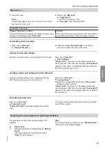
Страница 27: ...gs have been saved to the SD card as file type set Loading control unit settings from the SD card Settings and parameters can be reloaded from the SET file previously saved on the SD card Main menu SD card Load settings Select the required SET file from the File select window and start with OK Please wait is shown on the display during the saving process After this the message Successful appears T...

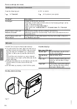
Страница 28: ...e relevant sensor 5 2 x OK opens the offset setting 6 for the required offset value 7 2 x OK to confirm Central fault message Fault relay If the Fault relay function is enabled and a fault occurs at the control unit the control unit will switch a potential free relay R4 Note on cascade The Fault relay is only enabled at the master control unit All faults that occur at the slave control units are t...

Страница 29: ...sabled Pasteu dur Duration of active pasteurisation RT stratif RT stratification Shows whether return stratification is enabled or disabled Fault relay Fault relay Shows whether the potential free fault relay is enabled or disabled Messages The display of status fault and warning messages depends on the system equipment level see also page 31 Service S1 to S8 Displays the temperature captured at t...

Страница 30: ...te total amount drawn is displayed For a realistic value the DHW circu lation volume must be deducted DHW circ TDHWcircRT S4 Pressing OK displays Minimum and Maximum Flow rate VFS Pressing OK displays Maximum and Total DHW circ pump PWM2 Pressing OK displays the hours run Operatn in h Pasteurisatn T FL S1 Pressing OK displays Minimum and Maximum T pasteu FL S2 Pressing OK displays Minimum and Maxi...

Страница 31: ...ration The following table shows some examples Messages Explanation Everything OK If no fault has occurred Version Displays the version of the control unit and selected hydraulic type Sensor fault Sensor fault for checking the cause of the fault see page 32 Fault A fault has occurred at the control unit for checking the cause of the fault see page 32 Note If a fault occurs in the appliance the LED...

Страница 32: ...ation Flow rate Flow sensor failure DHW heating DHW circ Thermal pasteurisation Heat meter count T DHW TDHW sensor failure DHW heating Cold start function DHW circ Thermal pasteurisation Heat meter count T DHW max ex ceeded Excessive temperature protection function DHW heating Automatic restart when TDHW TDHW set If the fault occurs frequent ly check buffer cylinder temperature and reduce if requi...

Страница 33: ...de mas ter or cascade slave Assign a different address to each subscriber Information on recommissioning After a repair the following occurs automatically Functions are reactivated Fault message is deleted Cascade is reorganised 1 Messages Fault Cause Remedy Short circuit Sensor The sensor indicated has suffered a short circuit Check the relevant sensor see page 36 EEPROM Internal fault Switch con...

Страница 34: ...mperature sensor S1 Check hydraulic connection Check the electrical connection cables and earthing Check flow temperature sensor S1 see page 36 Replace sensor if required Primary pump Check the primary pump Check hydraulic connection Check the electrical connection and cables see page 7 and separate instructions Check proper functioning Replace primary pump if required Fluctuating temperature on t...

Страница 35: ... Note The circulation pump will start automatically after the cause of the fault has been removed Undervoltage 160 V Overvoltage 253 V Check power supply 195 V U 253 V Motor temperature too high Check ambient and heat transfer medium tempera tures Circulation pump rotor is rotated by incorrect circu lation Ensure that incorrect circu lation e g due to other cir culation pumps in the sys tem is pre...

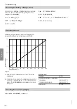
Страница 36: ...re Pt1000 Resistance in kΩ 1 4 1 100 0 10 20 30 40 50 60 70 80 90 1 3 1 2 1 1 Temperature in C Fig 14 1 Disconnect the relevant sensor and measure its resistance 2 Compare the result with the actual temperature for scanning see page 30 In the case of severe devi ation check the installation and replace the sensor if required Specification IP rating IP 53 Permissible ambient temperature Operation 2...

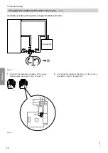
Страница 37: ...ayed 2 for DHW 3 OK to confirm 4 OK to confirm for Emerg mode act 5 for Yes 6 2 x OK to confirm Set the emergency speed so that the required set DHW temperature is shown under TDHW 7 for Emerg spd 8 OK to confirm Set the emergency speed 9 2 x OK to confirm Changing the rotational direction of the 3 way diverter valve Installation position with rotational direction in its factory setting Vitotrans ...

Страница 38: ...g 16 1 Ascertain the installation position of the 3 way diverter valve as shown in Fig 15 and 16 2 To change the rotational direction turn the connec tor shown in Fig 17 through 180 N L 1 S 180 Fig 17 Troubleshooting Changing the rotational direction of the 3 way cont 5517 095 GB Diagnosis ...

Страница 39: ...R2 R3 A B Fig 18 A Control unit wiring chamber B Fuse 4 A 1 Open the control unit wiring chamber 2 A spare fuse B is included in the fuse holder Replace the fuse Troubleshooting Replacing the MCB fuse 5517 095 GB Diagnosis ...

Страница 40: ...ons in the system example PWM1 S4 PWM2 WW B C S1 S6 M R2 S5 S2 VFS US S1 KW PWM2 A B C A PWM1 R2 S8 B S1 PWM2 PWM1 R2 S8 S1 PWM2 Fig 19 System example System example individual appliance 5517 095 GB System examples ...

Страница 41: ...turn distribution set Type PBS Return distribution set accessories 3 way diverter valve Type PZS 3 way diverter valve integrated in the appli ance in the delivered condition S1 Flow temperature sensor heating water side T FL S2 DHW temperature sensor TDHW S4 Temperature sensor cold water or DHW circu lation return T CW TDHWcircRT S5 Optional Additional cylinder temperature sen sor for temperature ...

Страница 42: ...e 1 PWM1 R1 PWM2 R2 S1 VBus S4 S2 S5 S6 M 1 R2 1 PWM1 1 S2 1 R1 A E 1 S5 1 S4 M 1 VFS US A B C 1 R1 M 1 PWM1 VFS US 1 PWM1 R1 PWM2 R2 S1 VBus S4 S2 S5 S6 VFS US 1 S1 Fig 21 System example System example cascade 5517 095 GB System examples ...

Страница 43: ...trol unit in the Vitotrans 353 3 Not shown Slave control unit in the Vitotrans 353 4 Slave control unit in the Vitotrans 353 KW Cold water WW DHW PWM1 Primary pump PWM2 Secondary pump DHW circulation pump accessories R1 Cascade valve R2 Temperature dependent return stratification Only with return distribution set accessories S1 Flow temperature sensor heating water side T FL S2 DHW temperature sen...

Страница 44: ...60529 ensure through design installation Function type Type 1 B to EN 60730 1 Permiss ambient temperature 0 to 40 C Standby power consumption 1 W Current output VBus 60 mA Rated relay output breaking capacity at 230 V Semi conductor relays R1 to R3 1 1 A Potential free relay R4 4 1 A Total max 4 A Specification Specification 5517 095 GB Service ...

Страница 45: ...sen Man start Start T pasteu set Pasteu dur Pasteu day Pasteu time DHWcirc fl rt Type T ON Hysteres ΔT ON ΔT OFF TDHWcircON ΔT OFF DHWcirc runt DHWcirc pause Timer Pasteurisatn RT stratification RT stratif Type T ON Hysteres ΔT ON ΔT OFF Default settings Language Summer winter Date Time T display standby Factory setting SD card Manual mode Operator code Inputs outputs Overview of menu structure Me...

Страница 46: ...W circ Type DHWcirc sen Man start Start T pasteu set Pasteu dur Pasteu day Pasteu time DHWcirc fl rt Type T ON Hysteres ΔT ON ΔT OFF TDHWcircON ΔT OFF DHWcirc runt DHWcirc pause Timer Pasteurisatn RT stratification RT stratif Type T ON Hysteres ΔT ON ΔT OFF Default settings Lang Summer winter Date Time T display standby Factory setting SD card Manual mode Operator code Inputs outputs Overview of m...

Страница 47: ...ade Cont type Balance cascade No of slaves DHW Emerg mode Blocking prot Default settings T display standby Factory setting SD card Manual mode Operator code Inputs outputs Overview of menu structure Menu structure cascade slave control unit 5517 095 GB Service ...

Страница 48: ... 36 DHW circulation Function modes 21 Manual balancing DHW circulation pump 22 Setting 20 DHW setting 18 DHW temperature selection 24 Display backlighting 16 Display setting 18 Draw off rate 34 E Electrical connection 7 Emergency mode enable 37 F Factory settings restoring 36 Fault Acknowledging 32 Checking 32 Fault message 32 Fault messages 32 Fault relay 28 Faults SD card 33 With on screen displ...

Страница 49: ...settings 27 Possible displays 26 Saving control unit settings 27 Starting data recording 26 Terminating data recording 27 Secondary pump Connecting 7 Sensor faults 32 Sensors Balancing 28 Checking 36 Connecting 8 Set DHW temperature 24 Slave 47 Slave control unit 47 Spare fuse 39 Specification 44 Status messages Calling up 29 Pasteurisation 25 Summer wintertime changeover 17 Switching power on 14 ...

Страница 50: ...50 5517 095 GB ...

Страница 51: ...51 5517 095 GB ...

Страница 52: ... Limited Hortonwood 30 Telford Shropshire TF1 7YP GB Telephone 44 1952 675000 Fax 44 1952 675040 E mail info uk viessmann com Viessmann Werke GmbH Co KG D 35107 Allendorf Telephone 49 6452 70 0 Fax 49 6452 70 2780 www viessmann com 5517 095 GB Subject to technical modifications ...

Отзывы: