background image

Display
fault
code

Const.

Weath.-
comp.

System char-
acteristics

Cause

Remedy

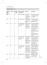
F8

X

X

Burner control
unit fault

The fuel
valve closes
too late.

Check the gas
train. Check both
control paths.
Press "

E

".

F9

X

X

Burner control
unit fault

Fan speed
too low dur-
ing burner
start

Check the fan,
check the fan
cables and sup-
ply, check the fan
control.
Press "

E

".

FA

X

X

Burner control
unit fault

Fan not at
standstill

Check the fan, fan
connecting cables
and fan control.
Press "

E

".

FC

X

X

Burner control
unit fault

Gas train
faulty or
faulty modu-
lation valve
control; or
flue gas path
blocked

Check the gas
train. Check the
flue gas system.
Press "

E

".

Fd

X

X

Burner control
unit fault

Faulty burn-
er control
unit or boiler
coding card

Check ignition
electrodes and
connecting
cables. Check
whether a strong
interference
(EMC) field exists
near the equip-
ment.
Press "

E

".

If the fault cannot
be removed,
check the boiler
coding card or re-
place it, if re-
quired or replace
the control unit.

Fault codes

(cont.)

82

Troubleshooting

5692

569

GB

Содержание Vitodens 300

Страница 1: ...uctions for heating engineers Vitodens 300 Type WB3A 4 2 to 13 0 kW Wall mounted gas fired condensing boiler Natural gas and LPG version For applicability see the last page VITODENS 300 5692 569 GB 1...

Страница 2: ...utes of that coun try Work on electrical equipment must only be carried out by a qualified elec trician The system must be commissioned by the system installer or a qualified per son authorised by the...

Страница 3: ...oving a separate fuse or by means of a mains isola tor Safeguard the system against unauthorised reconnection When using gas as fuel also close the main gas shut off valve and safeguard against unauth...

Страница 4: ...ay 72 Calling up fault codes from the fault memory fault history 73 Fault codes 74 Repairs 83 Function description Constant temperature control unit 93 Weather compensated control unit 94 Extensions f...

Страница 5: ...type only for operation with LPG 11 10 Function sequence and possible faults 11 11 Checking the static and supply pressure 13 12 Checking the combustion quality 15 13 Setting the maximum output 16 14...

Страница 6: ...gas equipment for soundness at operating pressure 23 27 Checking the ionisation current 24 28 Checking external LPG safety valve if required 29 Matching the control unit to the heating system 25 30 C...

Страница 7: ...via boiler fill drain valve A minimum sys tem pressure 0 8 bar Note If the control unit had not already been switched ON before filling began The diverter valve is in its central position and the sys...

Страница 8: ...n valves A and B and vent at mains pressure until no sound of escaping air can be heard 4 Close valves A and B and open the primary shut off valves Venting the heating system 1 Close the gas shut off...

Страница 9: ...unit 3 Check the system pressure Filling the siphon with water 1 Remove the retaining clip and siphon A 2 Fill the siphon with water 3 Fit siphon A and secure with the retaining clip Selecting the la...

Страница 10: ...mum combustion in accordance with the prevailing gas qual ity For natural gas there is consequently no adjustment required across the entire Wobbe range The boiler can be operated in the Wobbe index r...

Страница 11: ...e 2 In coding address 11 select value 9 In coding address 82 select value 1 operation with LPG Set code 11 9 and terminate code 2 4 Open the gas shut off valve Function sequence and possible faults Fo...

Страница 12: ...ion current check the elec trode adjustment and the gas pipe for airlocks Symbol A F4 Yes Burner in opera tion Stops below set boiler water tem perature and re starts Check flue gas system for sound n...

Страница 13: ...lushing 1 Close the gas shut off valve 2 Release the screw inside the test port PE A at the gas combination valve but do not remove it and connect the pressure gauge 3 Open the gas shut off valve 4 Ch...

Страница 14: ...bar 42 5 to 57 5 mbar Start up the boiler in excess of 57 5 mbar in excess of 57 5 mbar Install a separate gas governor down stream of the system and regulate the pressure to 20 mbar for natural gas o...

Страница 15: ...ced flue system for soundness see page 17 Check the ionisation electrode and connecting lead see page 20 Check the parameters of the combustion control unit see page 91 Note During commissioning the c...

Страница 16: ...h a b in the display select Full load 7 Check the CO2 content Should the actual value deviate by more than 1 from the above range imple ment the steps from page 15 pos sibly replace the burner 8 After...

Страница 17: ...A Combustion air aperture For balanced flue systems tested together with the wall mounted gas fired boiler some authorities waive the requirement for a soundness test overpressure test during commis...

Страница 18: ...as valve B ionisation elec trode C ignition unit D and earth connector E 4 Undo the fixing screws of gas sup ply flange F 5 Release four nuts G and remove the burner Please note Prevent damage to the...

Страница 19: ...s A 2 Release the three nuts B and remove the burner gauze assembly C 3 Remove the old burner gauze gas ket D 4 Insert a new burner gauze assem bly with a new gasket and secure with three nuts Note To...

Страница 20: ...a small brush not with a wire brush or emery paper Please note Never damage the wire gauze 3 Check clearances If the gaps are not as specified or the electrodes are damaged replace and align the elect...

Страница 21: ...th alka line cleaning agents with addi tional surfactants e g Fauch 600 Remove coatings and surface discolouration yellow brown with slightly acidic chloride free cleaning agents based on phos phoric...

Страница 22: ...in freely 2 Remove the retaining clip and the siphon 3 Clean the siphon 4 Fill the siphon with water and fit it to the boiler Position the retaining clip Checking the diaphragm expansion vessel and sy...

Страница 23: ...until the filling pres sure of a cool system is 0 1 to 0 2 bar higher than the inlet pressure of the diaphragm expansion ves sel Permissible operating pressure 3 bar Checking all gas equipment for so...

Страница 24: ...ol unit Press K and d simultaneously for at least 2 s With a b in the display select Full load Note The minimum ionisation current should be at least 4 A as soon as the flame is established approx 2 3...

Страница 25: ...eps to encode the gas type see page 91 For further encoding steps see page 39 System design 1 With without DHW heating with one heating circuit without mixer A1 Outside temperature sensor only for wea...

Страница 26: ...ure sensor Cylinder temperature sensor s Heating circuit pump lH Power supply extension kit aVG KM BUS A Maximum thermostat underfloor heating B Extension kit for a heating circuit with mixer Required...

Страница 27: ...e sensor s Heating circuit pump lH Power supply extension kit aVG KM BUS A Maximum thermostat underfloor heating B Extension kit for a heating circuit with mixer C Heat exchanger for system separation...

Страница 28: ...en sion or s Heating circuit pump for one heating circuit without mixer connection via external exten sion lH Power supply extension kit aVG KM BUS A Internal extension H1 or H2 or External extension...

Страница 29: ...nsor s Heating circuit pump lH Power supply extension kit aVG KM BUS LON LON communication modules for Vitotronic 200 and Vitotronic 050 LON cables and 2 LON terminal resistors A Extension kit for a h...

Страница 30: ...out mixer A1 solar collectors and Vitocell W 100 DHW cylinder type CVB installed adjacent to the boiler Outside temperature sensor aVG KM BUS A Solar Divicon B Collector temperature sensor C Vitosolic...

Страница 31: ...ake 2 to 3 minutes Setting up LON user numbers Adjust the user number via coding address 77 see below In a LON system the same number cannot be allocated twice Updating the LON user list Only possible...

Страница 32: ...erature via LON Code 97 2 The outside tem perature is re ceived via LON Set code 97 1 The outside tem perature is received via LON Set code 97 1 Implementing a user check in conjunction with the LON s...

Страница 33: ...or checking further users proceed as described under items 2 and 3 5 Press L and d simultaneously for approx 1 s The user check is completed Adjusting the heating curve only for weather compensated co...

Страница 34: ...loor heating systems B Heating curve slope for low tem perature heating systems according to the Energy Savings Order Germany Further details regarding the individual steps cont 34 Initial start up in...

Страница 35: ...1 Change the slope with coding address d3 in code 1 see page 39 Adjustable value 2 to 35 equals slope 0 2 to 3 5 2 Change the level in coding address d4 in code 1 see page 39 Adjustable value from 13...

Страница 36: ...ng circuit A1 heating circuit without mixer or 3 a 2r flashes in the display 4 d to select heating circuit M2 heating circuit with mixer 5 Adjust the set day temperature with rotary selector ts The va...

Страница 37: ...temperature 6 a b Change the value 7 d Confirm the value Instructing the system user The system installer must hand the operating instructions to the system user and instruct him her in the operation...

Страница 38: ...nance display extin guishes and the red fault indicator continues to flash Note An acknowledged maintenance message can be redisplayed by pressing d approx 3 s After maintenance has been carried out 1...

Страница 39: ...s codes are displayed as plain text Codes which are irrelevant due to the system equipment level or the setting of other codes will not be displayed 3 Confirm the value with a or b confirm with d The...

Страница 40: ...em design 2 3 4 1 heating circuit without mixer A1 and 1 mixer cir cuit M2 without DHW heating 00 6 System design 2 3 4 1 heating circuit without mixer A1 and 1 mixer cir cuit M2 with DHW heat ing Max...

Страница 41: ...inimum flow temperature limit 20 C C5 1 to C5 127 Minimum limit adjustable from 1 to 127 C Min flow temp M2 C5 20 Electronic minimum flow temperature limit 20 C C5 1 to C5 127 Minimum limit adjustable...

Страница 42: ...for approx 2 s confirm with d 2 Select the required coding address with a or b the address flashes Confirm with d the value flashes 3 Confirm the value with a or b confirm with d The display briefly s...

Страница 43: ...o Fb are scrolled for the heating circuit without mixer A1 then those for the heating circuit with mixer M2 Coding Coding in the delivered condition Possible change System designs 00 1 System design 1...

Страница 44: ...enance 23 1 to 23 24 Interval adjustable from 1 to 24 months 24 0 No Maintenance dis play 24 1 Maintenance display the address is automati cally set and must be manually reset after a service has been...

Страница 45: ...cir cuit pump Heating cir cuit without mixer Heating circuit pump Heating circuit with mixer Cylinder primary pump 0 Control funct Control funct Control funct Control funct 1 Control funct Control fun...

Страница 46: ...unct Control funct Control funct Control funct 1 Control funct Control funct Control funct OFF 2 Control funct Control funct OFF Control funct 3 Control funct Control funct OFF OFF 4 Control funct OFF...

Страница 47: ...ed condition Possible change Boiler burner 52 0 Without flow tempera ture sensor for low loss header 52 1 With flow temperature sensor for low loss head er automatic adjustment after recognition 53 1...

Страница 48: ...ng the boiler water tem perature is max 20 K higher than set DHW temperature 60 5 to 60 25 The difference between the boiler water tempera ture and the set DHW temperature is adjustable from 5 to 25 K...

Страница 49: ...t value 1 71 2 ON during DHW heating to set value 1 72 0 1DHW circulation pump ON according to DHW time program 72 1 OFF during DHW heating to set value 2 72 2 ON during DHW heating to set value 2 73...

Страница 50: ...over 81 0 Manual summer winter time changeover 81 2 The radio clock module will be recognised auto matically 81 3 Accept time via LON 82 0 Operation with natural gas 82 1 Operation with LPG only adjus...

Страница 51: ...rface automatic recognition 97 0 1The outside tempera ture of the sensor con nected to the control unit is utilised internally 97 1 The outside temperature is accepted by the LON BUS 97 2 The outside...

Страница 52: ...rom 0 to 40 K Boiler circuit mixer circuit A0 0 1Without remote con trol A0 1 With Vitotrol 200 auto matic recognition A0 2 With Vitotrol 300 auto matic recognition A3 2 1 Outside temperature below 1...

Страница 53: ...ge Boiler circuit mixer circuit A4 0 1With frost protection A4 1 No frost protection this setting is only possible if code A3 9 has been selected Note When selecting a value below 1 C there is a risk...

Страница 54: ...thout heating circuit pump logic function A5 1 to A5 15 With heating circuit pump logic function Heating circuit pump OFF if see the following table Parameter address A5 With heating circuit pump logi...

Страница 55: ...es the cooling down of an average building into considera tion A7 0 1Without mixer econo my function A7 1 With mixer economy function extended heat ing circuit pump logic Heating circuit pump also OFF...

Страница 56: ...it and for the heating cir cuit heating with room temperature hook up must be encoded Room influencing factor 8 2 b2 0 Without room influence b2 1 to b2 64 Room influence factor adjustable from 1 to 6...

Страница 57: ...ustable from 1 to 127 C C6 74 1Electronic maximum flow temperature limit 74 C C6 0 to C6 127 Maximum temperature limit adjustable from 1 to 127 C d3 14 1Heating curve slope 1 4 d3 2 to d3 35 Heating c...

Страница 58: ...mode E6 0 to E6 100 Maximum speed adjusta ble from 0 to 100 of max speed min speed defaulted by the boiler coding card E7 30 1Min speed of the vari able speed pump 30 of max speed E7 0 to E7 100 Minim...

Страница 59: ...eport to be provided by the heating contractor must contain the follow ing heat up details Heat up data with respective flow tem peratures Max flow temperature achieved Operating condition and outside...

Страница 60: ...he value selected as set room temperature if the system operates with the standard room tem perature F9 10 to F9 60 Limit for raising the set room temperature to the value selected for stan dard mode...

Страница 61: ...nternal cir culation pump is permanently OFF F6 1 to F6 24 In the operating mode DHW only the internal circulation pump will be started 1 to 24 times per day for 10 min respec tively F7 25 3Internal c...

Страница 62: ...2 Press e Confirm Standard setting Yes with d With a or b Standard setting Yes or Standard setting No can be selected Resetting codes to the delivered condition cont 62 Coding 5692 569 GB...

Страница 63: ...for approx 2 s Press d 73 User check in conjunc tion with LON system L and d simultaneously for approx 2 s L and d simulta neously 32 Emissions test function S F and E simulta neously for approx 2 s F...

Страница 64: ...Low loss header Low loss header Boiler coding card Brief scan 1 to Brief scan 8 Display screen Brief scan Boiler coding card N A N A X X X X 1 Software version Control unit Version Boiler EEPROM Versi...

Страница 65: ...0 w o 1 Vitotr ol 200 2 Vitotr ol 300 Software version Remote control Remote control 0 w o 1 Vitotr ol 200 2 Vitotr ol 300 Software version Remote control Internal circulation pump Heating circuit pu...

Страница 66: ...Software version ext extension Software version Cascade module E 0 No ext demand or operating mode change over 1 Ext de mand or operating mode change over active 0 No ext blocking 1 Ext blocking activ...

Страница 67: ...t level the following relay outputs can be con trolled Display Explanation Base load Burner modulation lower output Full load Burner modulation upper output Int pump ON Int pump output 20 ON Heating v...

Страница 68: ...level the following relay outputs can be con trolled Display Explanation 1 Burner modulation lower output 2 Burner modulation upper output 3 Diverter valve set to heating mode 4 Valve in central posi...

Страница 69: ...a holiday program has been set up Departure date Date Return date Date Outside temperature C Actual value Boiler water temp C Actual value Flow temperature C Actual value only for mixer circuit M2 Sta...

Страница 70: ...ircuit pump OFF or ON Display only if a Vitosolic is installed Solar circuit pump h Hours run Various languages The respective languages can be selected as permanent display language with d Constant t...

Страница 71: ...hours run 030529 1 Burner starts 001417 h Hours run solar circuit pump 002850 Solar energy in kW h Scanning operating conditions and sensors cont 71 Service scans 5692 569 GB 1Reset hours run and bur...

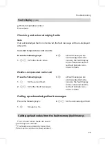
Страница 72: ...ure control units In case of faults the fault code and fault symbol will be displayed at the programming unit Weather compensated control unit The display flashes Fault if a fault message is issued Pl...

Страница 73: ...ompensated control unit Press the following keys 1 c for the current fault 2 a b for further fault messages 3 d all fault messages are acknowledged simulta neously the fault display will be cancelled...

Страница 74: ...page 83 18 X X Regulates as if the outside temperature was 0 C Outside tem perature sensor lead broken Check the outside temperature sen sor see page 83 20 X X Regulates without flow temperature senso...

Страница 75: ...tem perature sensor lead broken Check the flow temperature sen sor 50 X X No DHW heat ing Cylinder temperature sensor com fort sensor primary sen sor shorted out Check sensors see page 85 58 X X No D...

Страница 76: ...ol mode Solar Cylin der tempera ture sensor shorted out Check sensor 9C X X Control mode Cylinder temperature sensor lead broken Check sensor 9F X X Control mode Solar control unit fault message See s...

Страница 77: ...bA X Mixer M2 con tinues to regu late Communica tion fault extension kit for mixer cir cuit M2 Check the exten sion kit connec tions and coding Start the exten sion kit bC X Control mode without remo...

Страница 78: ...delivered condi tion Switch 2 OFF delivered condi tion C6 X Control mode max pump speed Communica tion fault variable speed circu lation pump heating circuit M2 Check coding ad dress E5 set tings chec...

Страница 79: ...ture sen sor heating cir cuit A1 db X Control mode without room influence Room tem perature sensor heat ing circuit M2 shorted out Check the room temperature sen sor heating cir cuit M2 dd X Control m...

Страница 80: ...lies outside the permissi ble range during cali bration Check the ionisa tion electrode and lead Press E EA X X Burner control unit fault The ionisa tion current lies outside the permissi ble range d...

Страница 81: ...nit fault The tem perature lim iter has responded Check the heating system fill level Check the circula tion pump Vent the system Check the tem perature limiter and connecting cables Press E F3 X X Bu...

Страница 82: ...ck the fan fan connecting cables and fan control Press E FC X X Burner control unit fault Gas train faulty or faulty modu lation valve control or flue gas path blocked Check the gas train Check the fl...

Страница 83: ...the control unit if the equip ment will not re start FF X X Burner blocked or in a fault state Strong inter ference EMC field nearby or in ternal fault Start the boiler again Switch OFF the control u...

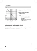
Страница 84: ...ected plug and compare it with the curve 3 Where actual values strongly devi ate from the curve values discon nect the wires at the sensor and repeat test immediately at the sen sor 4 Depending on the...

Страница 85: ...ture sensor Pull the leads off boiler temperature sensor A and check the resis tance Cylinder temperature sensor Pull plug from the cable harness on the control unit and check the resis tance Flow tem...

Страница 86: ...ersed in the heating water risk of scalding Drain the boiler before repla cing the sensor Checking the flue gas temperature sensor The flue gas temperature sensor locks out the boiler when the permiss...

Страница 87: ...ull the leads from flue gas tem perature sensor A 2 Check the sensor resistance and compare it with the curve 3 Replace the sensor in case of severe deviation Repairs cont 87 Troubleshooting 5692 569...

Страница 88: ...er temperature is below approx 75 C Pull the leads off temperature limiter A Check the continuity of the tempera ture limiter with a multimeter Remove the faulty temperature lim iter Install a new tem...

Страница 89: ...Checking the fuse 1 Switch OFF the power 2 Release the lateral closures and pivot the control unit down 3 Remove cover A 4 Check fuse F1 Repairs cont 89 Troubleshooting 5692 569 GB...

Страница 90: ...e rotational direction of the mixer motor during its self test Then set the mixer manually to Open again Note The flow temperature sensor must now sense a higher temperature If the temperature falls e...

Страница 91: ...e coding addresses of the parameters is open 4 Select the required coding address with a or b see the following table and change the value 5 Select 11 9 to increase the value of the coding address the...

Страница 92: ...tart capacity correction adjustable from 16 to 14 One step equals 2 85 0 Standard mode 85 1 Manual calibration of the combustion control unit The red fault indicator also flashes during cali bration T...

Страница 93: ...at a boiler water temperature of 100 C DHW heating DHW heating will be activated if the cylinder temperature is 2 5 K below the set cylinder temperature The burner the circulation pump and the three w...

Страница 94: ...ain locks out the burner control unit at a boiler water temperature of 100 C DHW heating DHW heating will be activated if the cylinder temperature falls 2 5 K below the set cylinder temperature The bu...

Страница 95: ...day program D Information E Heating programs F Standard room temperature G Economy mode H Party mode K Standard setting L Confirmation M Setting values N DHW temperature O Emissions test function P Re...

Страница 96: ...function is allocated via coding address 53 Central fault message code 53 0 Cylinder primary pump coding 53 3 DHW circulation pump code 53 1 Heating circuit pump for a heating circuit without mixer co...

Страница 97: ...put sK The function is allocated via coding address 53 Central fault message code 53 0 Cylinder primary pump coding 53 3 DHW circulation pump code 53 1 Heating circuit pump for a heating circuit witho...

Страница 98: ...t without mixer sA Cylinder primary pump sK DHW circulation pump f Power supply g Fault notification aVD External blocking terminals 2 3 External demand terminals 1 2 External operating mode chan geov...

Страница 99: ...usly via the extension sK DHW circulation pump f Power supply aVD External blocking terminals 2 3 External demand terminals 1 2 External operating mode chan geover terminal 1 2 The allocation of the E...

Страница 100: ...mixer With coding address d5 you can select in which direction the change over should be made for each heating circuit Coding The operating mode changeover af fects d5 0 Changeover in the direction o...

Страница 101: ...signal should have on the connected circula tion pumps In coding address 9b you can select the minimum set boiler water tem perature in case of external demand Venting program Note Close the gas shut...

Страница 102: ...e system can be filled comple tely Filling with the control unit switched ON If the system is to be filled with the control unit switched ON the change over valve will be moved to its central position...

Страница 103: ...file Diagram 1 DIN 4725 part 4 code F1 1 Temperature profile Diagram 2 ZV parquet and flooring technology code F1 2 Temperature profile Diagram 3 code F1 3 Control functions cont 103 Function descript...

Страница 104: ...Temperature profile Diagram 4 code F1 4 Temperature profile Diagram 5 code F1 5 Temperature profile Diagram 6 code F1 6 delivered condition Control functions cont 104 Function description 5692 569 GB...

Страница 105: ...2 content and air factor is illustrated in the follow ing table Air factor CO2 O2 content Air factor O2 content CO2 content for natur al gas E CO2 content for natur al gas LL CO2 content for LPG P 1 2...

Страница 106: ...sor aA Ionisation electrode aG Flue gas temperature sensor d Stepper motor for diverter valve fJ Temperature limiter gF Ignition unit a Fan motor a Modulation coil Connection and wiring diagrams inter...

Страница 107: ...A1 Main PCB A2 Power supply unit Connection and wiring diagrams external connections 107 Designs 5692 569 GB...

Страница 108: ...button Outside temperature sensor Flow temperature sensor low loss header Cylinder temperature sensor plug on the cable harness s Internal circulation pump dG Gas solenoid valve f Power supply lH Powe...

Страница 109: ...038 Connection line for the dia phragm expansion vessel 039 Back panel lid 040 Clip nut 5 pieces 041 Plug in connector gaskets set 052 Burner gauze 053 Burner gauze gasket 058 Fan outlet gasket 059 Fa...

Страница 110: ...nstallation instructions 151 Service instructions 152 Operating instructions for con stant temperature mode 153 Operating instructions for weather compensated mode 155 Touch up spray paint Vitowhite 1...

Страница 111: ...Parts lists cont 111 Parts lists 5692 569 GB...

Страница 112: ...Parts lists cont 112 Parts lists 5692 569 GB...

Страница 113: ...Parts lists cont 113 Parts lists 5692 569 GB...

Страница 114: ...Parts lists cont 114 Parts lists 5692 569 GB...

Страница 115: ...Parts lists cont 115 Parts lists 5692 569 GB...

Страница 116: ...for LPG mbar 42 5 57 5 mbar Tick gas type Carbon dioxide content CO2 at the lower rated output vol at the upper rated output vol Oxygen content O2 at the lower rated output vol at the upper rated out...

Страница 117: ...Maintenance ser vice Maintenance service Maintenance service Maintenance ser vice Commissioning service reports cont 117 Commissioning service reports 5692 569 GB...

Страница 118: ...for LPG mbar 42 5 57 5 mbar Tick gas type Carbon dioxide content CO2 at the lower rated output vol at the upper rated output vol Oxygen content O2 at the lower rated output vol at the upper rated outp...

Страница 119: ...Maintenance ser vice Maintenance service Maintenance service Maintenance ser vice Commissioning service reports cont 119 Commissioning service reports 5692 569 GB...

Страница 120: ...for LPG mbar 42 5 57 5 mbar Tick gas type Carbon dioxide content CO2 at the lower rated output vol at the upper rated output vol Oxygen content O2 at the lower rated output vol at the upper rated outp...

Страница 121: ...Maintenance ser vice Maintenance service Maintenance service Maintenance ser vice Commissioning service reports cont 121 Commissioning service reports 5692 569 GB...

Страница 122: ...lative to the max load with with HuB Natural gas E 9 45 kWh m3 34 02 MJ m3 m3 h 1 77 Natural gas LL 8 13 kWh m3 29 25 MJ m3 m3 h 2 05 LPG 12 79 kWh kg 46 04 MJ kg m3 h 1 31 Product ID _ 0085 BO 0338 P...

Страница 123: ...ty by an authorised body according to EMVG article 10 2 Certificate number E9 02 08 1730 This product complies with the requirements of the Efficiency Directive 92 42 EEC for Condensing boilers The pr...

Страница 124: ...fol lowing product meets the NOx limits specified by the first BImSchV paragraph 7 2 Germany Vitodens 300 Allendorf 18 01 05 Viessmann Werke GmbH Co KG pp Manfred Sommer Manufacturer s certificate ac...

Страница 125: ...sion kit for heating circuit with mixer 90 Extension external 98 99 internal 96 97 External blocking 101 External demand 101 F Fault display design 72 Fault history 73 Fault memory 73 Faults 72 Fillin...

Страница 126: ...unction 102 Service level overview 63 Setting the date 10 Setting the output 16 Setting the time 10 Setting up LON user numbers 31 Siphon 9 22 Soundness test balanced flue system 17 Specification 122...

Страница 127: ...127 5692 569 GB...

Страница 128: ...friendly chlorine free bleached paper 5692 569 GB Subject to technical modifications Viessmann Werke GmbH Co KG D 35107 Allendorf Telefon 49 6452 70 0 Telefax 49 6452 70 2780 www viessmann com Viessm...

Отзывы: