Technical Data
8
VITOROND 200, VD2A
Clearances to Combustibles
Boiler model
VD2A-
125
160
195
230
270
Top
6” / 150 mm
Sides
6” / 150 mm
Flue (oil)
9” / 229 mm
Flue (gas)
6” / 150 mm
Front
6” / 150 mm
Floor
non-combustible
H
Avoid air contamination by halogenated
hydrocarbons (e.g. as in sprays, paints,
solvents and cleaning agents)
H
Avoid very dusty conditions
H
Avoid high levels of humidity
H
Protect against frost and ensure good
ventilation
Otherwise, the system may suffer faults and
damage. In rooms where air contamination
through halogenated hydrocarbons may
occur, install the boiler only if adequate
measures can be taken to provide a supply
Maintain 1” air clearance from uninsulated
hot water pipes to combustible material.
Boiler must not be installed on combustible
floor material.
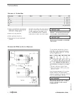
Recommended Minimum Service Clearances
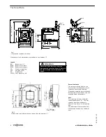
The combustion chamber door is factory
assembled to hinge on the left-hand side.
A right-hand hinge is feasible by rebuilding
the door hinge hardware.
Boiler
model
VD2A-
125
160
195
230
270
a
1
in
mm
47¼
1200
55
1400
63
1600
71
1800
79
2000
b
2
Dependent on burner model
Inch dimensions are rounded to the nearest
¼”.
1
Minimum clearance in front of boiler
2
Burner height [plus 8” (200 mm) for door
clearance to wall].
Front clearances (dimension “a”) will allow
for easy removal of flue gas turbulator
inserts, as well as for full insertion of bristle
brush for heat exchanger cleaning.
Minimum side clearance of 20” / 500 mm
must be maintained for side-mounted
Vitotronic control.
5
3
5
4
7
8
7
v
1
.2
IMPORTANT
IMPORTANT
20” /
500 mm
20” / 500 mm
24” /
600 mm
170 mm
17” /
430 mm
8” / 200 mm
Fig. 4
6¾” /
Top View
IMPORTANT


