19
5285 429 - 03
Vitorond 200, VD2 Series 320 to 1080 Installation
Assembly
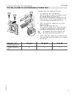
Flue Gas Turbulators and Combustion Chamber Door
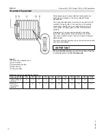
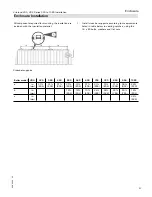
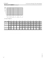
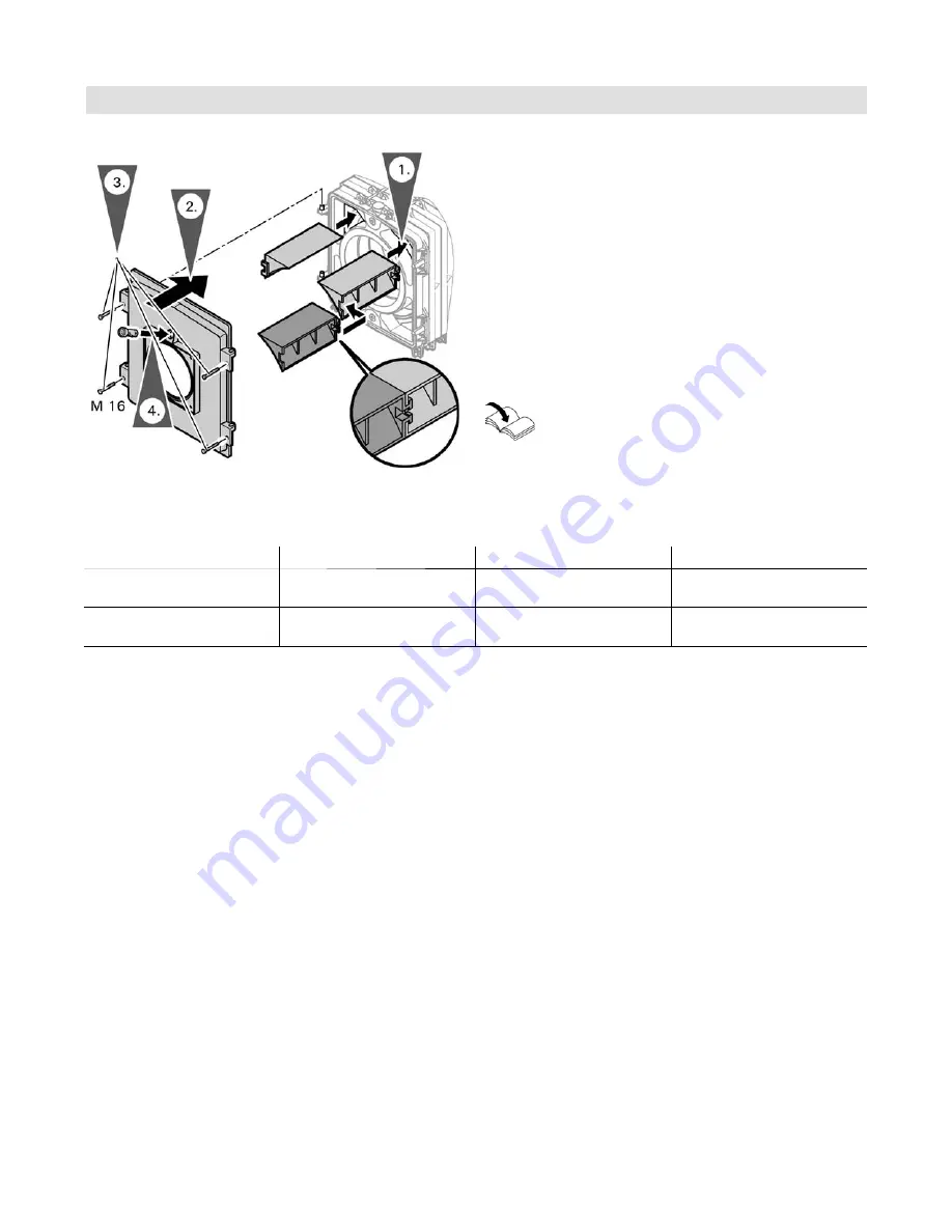
1. For models VD2-320 to VD2-860 only:
Insert the respective number of turbulators into each
flue gas passageway (see table below).
Push the first turbulator element approximately one
third of the way into the flue gas passageway, hook
in the second and third elements and push in.
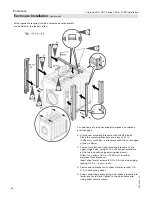
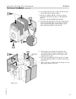
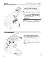
2. Attach the combustion chamber door to the front
section and align.
Observe the hinge side of the door.
The combustion chamber door is factory assembled
to hinge on the left-hand side. A right-hand hinge
is feasible by rebuilding the door hinge hardware.
3. Tighten combustion chamber door with M 16 screws.
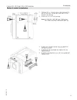
4. Insert sight glass into provided opening in combustion
chamber door.
Boiler model VD2-
320 to 440
500 and 560
630 to 860
Turbulator elements per
flue gas passageway
3
2
1
Turbulator elements per
boiler
12
8
4
Turbulators may not be exactly as illustrated.
See Installation Instructions Supplement for
Door Safety Switch (oil-fired boilers only).

