background image

for use by heating contractor

Please file in Service Binder

Read and save these instructions for future 

reference.

IMPORTANT

Product may not be exactly as shown

5285 429 - 03  12/2014

Installation Instructions

VITOROND 200

Vitorond 200

VD2 Series

Oil-/Gas-fired boiler

Heating input:  1255 to 4387 MBH 

 (368 


to 

1285 

kW)

Working on the equipment

The installation, adjustment, service and

maintenance of this product must be performed

by a licensed professional heating contractor,

who is qualified and experienced in the installation, 

service and maintenance of hot water heating 

boilers. There are no user serviceable parts on the 

boiler, burner, or control.

Ensure main power supply to equipment, the

heating system and all external controls has been

deactivated. Close main oil or gas supply valve.

Take precautions in all instances to avoid

accidental activation of power during service work.

Improper installation, service or maintenance can

cause product/property damage, severe personal

injury, and/or loss of life.

IMPORTANT

Please ensure that these instructions are read and

understood before commencing installation and 

start-up. Failure to comply with these Installation 

Instructions will render all warranties null and void.

Содержание VD2-1080

Страница 1: ...the installation service and maintenance of hot water heating boilers There are no user serviceable parts on the boiler burner or control Ensure main power supply to equipment the heating system and all external controls has been deactivated Close main oil or gas supply valve Take precautions in all instances to avoid accidental activation of power during service work Improper installation service...

Страница 2: ...equipment For a listing of chemicals which cannot be stored in or near the boiler room please see section entitled Mechanical Room in this manual Advice to owner Once the installation work is complete the heating contractor must familiarize the system operator ultimate owner with all equipment as well as safety precautions requirements shutdown procedure and the need for professional service annua...

Страница 3: ...berglass dust and contact with skin and eyes Use NIOSH approved dust mist respirator Wear long sleeved loose fitting clothing gloves and eye protection Wash work clothes separately from other clothing Rinse washer thoroughly Operations such as sawing blowing tear out and spraying may generate airborne fiber concentration requiring additional protection First aid measures If eye contact occurs flus...

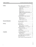
Страница 4: ...ant Regulatory and Safety Requirements 7 Codes 8 Mechanical room 8 Working on the equipment 8 Technical literature 8 Installation tools and materials 8 About these Installation Instructions 9 Product Information 9 Mechanical Room 10 Minimum Clearances 10 Minimum Clearances to Combustibles 10 Boiler model VD2 10 Recommended Minimum Service Clearances 10 Boiler Set up and Location 11 Transport into ...

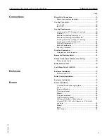
Страница 5: ...tems Inc 24 Selkirk Metalbestos 24 Security Chimneys 24 Flue Gas Connection 24 Flue gas test point location 24 Removal of Existing Boiler 25 Safety Connections and Pressure Testing 26 Pressure relief valve 26 Boiler Pressure Test 26 Low Water Cut off LWCO 26 Enclosure Installation 27 Boiler model VD2 27 Boiler Control Installation 31 Enclosure Installation 32 Burner Installation 33 Combustion cham...

Страница 6: ...l Data 39 Boiler Model 39 Input oil 39 Input gas 39 Output oil gas 39 Combustion efficiency oil 39 Combustion efficiency gas 39 Thermal efficiency oil 39 Thermal efficiency gas 39 Number of cast iron sections 39 Cast iron block dimensions 39 Cast iron section dimensions 39 Technical Data 40 Boiler Model 40 Dimensions with insul jacket 40 Weight 40 Overall weight 40 Boiler water content 40 Max boil...

Страница 7: ... the hard wired carbon monoxide detector with alarm and battery back up may be installed on the next adjacent floor level b In the event that the requirements of this subdivision can not be met at the time of completion of installation the owner shall have a period of thirty 30 days to comply with the above requirements provided however that during said thirty 30 day period a battery operated carb...

Страница 8: ...ocated must not exceed 104 F 40 C Working on the equipment The installation adjustment service and maintenance of this boiler must be performed by a licensed professional heating contractor who is qualified and experienced in the installation service and maintenance of hot water boilers There are no user serviceable parts on the boiler burners or control Note The completeness and functionality of ...

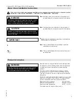
Страница 9: ... excess of those listed will result in damages and will render warranty null and void About these Installation Instructions Take note of all symbols and notations intended to draw attention to potential hazards or important product information These include WARNING CAUTION and IMPORTANT See below IMPORTANT Note Warnings draw your attention to the presence of potential hazards or important product ...

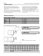
Страница 10: ...ted hot water pipes to combustible material Recommended Minimum Service Clearances Boiler model VD2 320 380 440 500 560 630 700 780 860 950 1080 a Minimum Clearance in front of boiler in mm 65b 1660 70 1790 76 1920 81 2050 86 2180 91 2310 96 2440 101 2570 106 2700 111 2830 117 2960 b Minimum Clearance on boiler side in mm 20 500 20 500 20 500 20 500 20 500 20 500 20 500 20 500 20 500 20 500 20 500...

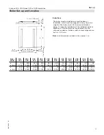
Страница 11: ...1830 77 1955 82 2080 86c 2205 91c 2330 96b 2460 101b 2580 The boiler must be installed on a levelled base or foundation which must be designed to carry the entire weight of the boiler water fill burner and attached piping To ease the installation of the individual sections angle iron or flat steel may be incorporated into the concrete foundation Surface width of steel strips should be 4 in 100 mm ...

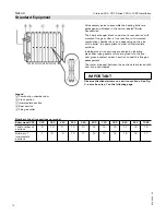
Страница 12: ... are packaged and shipped in the carton labeled Boiler Accessories The heat exchanger block consists of a rear section with mounted flue gas collar a front section with mounted combustion chamber door and depending on the size of the boiler the appropriate number of intermediate sections Individual cast iron sections are sealed by inserting glass fiber rope gaskets which are glued into the pre cas...

Страница 13: ...Ensure push nipples are inserted evenly by tapping in a cross wise fashion Remove any burrs if necessary 7 Prepare an intermediate section according to steps 1 through 6 Arrows on the intermediate section must point toward the rear section Legend A Not to be installed on rear section B Not for the last to be installed intermediate section C Remove flanges from rear section prior to boiler assembly...

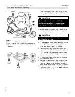
Страница 14: ... tipping 10 Mount intermediate section with wood or rubber mallet by tapping it onto the push nipples of the rear section Do not hammer in place 11 Insert the two main draw tool rods from the rear section to the front section into the upper and lower push nipple ports 12 Slide pressure flanges onto the draw tool rods and attach locking plates as shown 13 Attach pressure nuts and align both paralle...

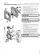
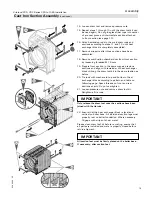
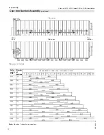
Страница 15: ...ections and align with remainder of heat exchanger block utilizing the draw tool kit in the same fashion as before 20 Tie rods with washers to top and bottom of heat exchanger block according to pattern and table on following page Space threads on front and rear sections evenly Do not overtighten 21 Loosen pressure nuts and remove draw tool kit Retighten all tie rods IMPORTANT Only release the dra...

Страница 16: ...ion 5285 429 03 16 Assembly Cast Iron Section Assembly continued Top view Side view Rear section Boiler front Placement of tie rods Note Number 1 refers to rear section Tie rod layout 19 and 24 in 480 and 610 mm Number of sections Boiler model VD2 ...

Страница 17: ...ion pipe through lower nipple ports 3 Insert supply nipple into R c in opening on rear cast iron section and install supplied fill and drain valve IMPORTANT Ensure that distribution pipe openings are facing upward Ensure that distribution pipe openings are facing upward Front section a max of 9 32 in 7 mm R 2 in plug Rear section R c in 4 Apply hemp and pipe dope to R 2 in plugs and insert into op...

Страница 18: ...tach a pressure gage 0 150 psig range to safety header as well as another automatic air vent watch for proper pressure rating to bleed all air properly from safety header 4 Fill pressure vessel with room temperature water and check for proper venting of air 5 The minimum hydrostatic test pressure must be 110 psig the maximum at 1 times the maximum operating pressure of the boiler not to exceed 120...

Страница 19: ... chamber door to the front section and align Observe the hinge side of the door The combustion chamber door is factory assembled to hinge on the left hand side A right hand hinge is feasible by rebuilding the door hinge hardware 3 Tighten combustion chamber door with M 16 screws 4 Insert sight glass into provided opening in combustion chamber door Boiler model VD2 320 to 440 500 and 560 630 to 860...

Страница 20: ...mediately downstream of the circulation pump in the heating circuit supply as a mechanical break is recommended to prevent water from flowing unintentionally to space heating circuits during DHW priority or summer operation when only DHW is produced WARNING Do not install an isolation valve between boiler and safety header Discharge pipe must be oriented to prevent scalding of attendants IMPORTANT...

Страница 21: ...return connection metric Boiler supply connection metric System return header ANSI 4 in System supply header ANSI 4 in Return temperature elevation Legend A Low water cut off standard equipment B Shunt pump C Flow check valve D Location of Honeywell aquastat to control boiler pump E Location of aJ sensor installed in stainless steel well All piping field supplied Install 100 boiler flow package as...

Страница 22: ...eeching outlet located at the rear of the boiler Never operate boiler without an installed venting system which safely vents all products of combustion to the outdoors The vent system must comply with all applicable local and or national codes Vitorond 200 VD2 boilers are Category I boilers as defined in ANSI Z21 13 when used with natural gas Venting systems shall be sized and constructed in accor...

Страница 23: ... ft 1 2 m H Insulate vent pipe to reduce cooling of flue gas H Terminate venting system outside with approved termination at least 6 ft 1 8 m above boiler Vent pipe must extend at least 3 ft 91 cm above the point where it passes through the roof Vent termination must be at least 2 ft 61 cm higher than any portion of the building within 10 ft 3 m horizontal and vent termination must be at least 2 f...

Страница 24: ...y III for single wall vertical venting of the Vitorond 200 boiler For more details on the positive pressure venting option see the Viessmann installation instructions for the positive pressure venting system The following manufacturers may be contacted for suitable stainless steel chimneys ProTech Systems Inc 26 Gansevoort Street Albany NY 12202 Tel 518 463 7284 Fax 518 463 5271 Toll free 1 800 76...

Страница 25: ...ol relief opening 5 minutes of high fire full load burner operation Use the flame of a match or a candle or an approved test 6 After it has been determined that each appliance remaining connected to the common venting system properly vents when tested as outlined above return doors windows exhaust fans fireplace dampers and any other gas burning appliance to their previous condition of use 7 Any i...

Страница 26: ... tank 3 Connect hose to boiler drain valve and fill boiler slowly until pressure gage indicates max 120 psig 827 kPa Boiler Pressure Test Low Water Cut off LWCO If boiler is installed above radiation level a low water cut off device of approved type standard equipment must be installed in all instances The approved low water cut off device must be installed by the mechanical contractor where requi...

Страница 27: ...6 x 80 bolts washers and flat nuts Crossbar supports Boiler model VD2 320 380 440 500 560 630 700 780 860 950 1080 a in mm 31c 805 31c 805 31c 805 31c 805 31c 805 31c 805 31c 805 31c 805 31c 805 36c 932 26c 679 b in mm 19c 502 19c 502 19c 502 24c 628 24c 628 29c 755 29c 755 19c 502 c in mm 24c 628 All components required for mounting the insulation are included with the insulation material Boiler ...

Страница 28: ...embly are included in the jacket carton For positions of cross bar supports please see table on previous page 2 Attach rear mounting brackets with the M 8 bolts Place the mounting brackets at a span of 41 in 1044 mm outside in alignment with the outer edges of the tie bar s 3 Fasten front left and right mounting brackets to the upper hinge bolts using M 12 nuts longer extenders at the top and with...

Страница 29: ...ear section insert the insulation mat underneath the assembled cast iron block Push and or pull towards front section until insulation mat is underneath entire length of cast iron block Boiler front 9 Insert hinges of side panels into the slots of the mounting brackets according to table below Slide mid panel models VD2 500 to VD2 1080 only as required to left or right 10 Insert right rear panel a...

Страница 30: ...60 630 700 780 860 950 1080 a in mm 24c 628 24c 628 24c 628 19c 502 19c 502 19c 502 24c 628 24c 628 24c 628 29c 755 19c 502 b in mm 19c 502 24c 628 24c 628 19c 502 19c 502 19c 502 24c 628 24c 628 29c 755 29c 755 19c 502 c in mm 19c 502 24c 628 29c 755 24c 628 29c 755 29c 755 29c 755 24c 628 d in mm 29c 755 Boiler front Side panel arrangement ...

Страница 31: ... Install burner harness bracket and tighten the two supplied screws 5 Install top mounting hole cover with two supplied self tapping screws 1 Drill four Ø d in 3 mm holes on the side panels A and B as shown For left side mount use a mirror image of the drawing 2 Punch a Ø 7 8 in 22 mm opening Note On VD2 500 560 630 and 1080 boilers the bracket mounting overlaps side panel B ...

Страница 32: ...tallation and orientation of all cabling and capillaries ensure placement away from high heat sources such as the vent the chimney or supply return piping For electrical and boiler control connections see Installation Instructions of boiler control 1 Mount top panel via hooks into side panels 2 Attach mid top panels models VD2 500 and up with hook to side panels not shown 3 Secure rear of top pane...

Страница 33: ...tion burner specifying the fuels Please see separate burner selection chart for Vitorond 200 VD2 boiler series in the Technical Data Manual Viessmann has made Weishaupt and Riello burners standard on all Vitorond 200 VD2 boilers for details see Technical Data Manual and or Weishaupt burner manuals supplied with burner Only oil or gas fired burners of the approved type can be utilized with the Vito...

Страница 34: ...ws Gas fired 10 volume CO2 280 F 138 C net stack temperature CO in ppm 50 Oil fired 13 volume CO2 300 F 149 C net stack temperature smoke spot 0 1 on the Bacharach Scale The maximum input published for each boiler size must not be exceeded Vitorond 200 VD2 with Viessmann Vitotronic controls To further protect the Vitorond 200 VD2 from dew point corrosion the following minimum inputs on a 2 stage b...

Страница 35: ...NG The boiler must not be located in areas or rooms where chemicals are stored or aggressive vapors from i e bleach hair spray methyl chloride carbon tetrachloride or perchloroethylene or high dust levels or humidity levels are present Heat exchanger corrosion might occur and reduce the lifetime of the boiler significantly If above criteria are not properly observed and boiler damage results any w...

Страница 36: ...chanical room are open j Ensure the heating system has been filled with water and is completely purged of air j Check cold fill pressure of heating system j Check oil supply or proper natural or propane gas supply pressure j Ensure proper barometric draft regulator is installed field supplied j Ensure clean out openings near flue gas collar are closed tightly Ensure that spring loaded flow check v...

Страница 37: ... the control system utilized reprogramming of the control system might be necessary in the event of lengthy power interruption Initial start up Initial start up must be performed by qualified personnel values and calibrations specified in the Technical Data section on page 36 in this manual are to be recorded at this time Instructing the system user The installer of the system is responsible to en...

Страница 38: ...rated air circulation must be equipped with flow control valves or other automatic means to prevent gravity circulation of the boiler water during the cooling cycle Check installation instructions of chiller manufacturer carefully for additional requirements Cooling season starts Close valve V1 and open valve V2 Heating season starts Close valve V2 and open valve V1 A metal tag should be attached ...

Страница 39: ... 10 11 12 13 14 15 16 17 18 19 Cast iron block dimensions Length in mm 57 1450 62 1580 67 1710 72 1840 77b 1970 82b 2100 88 2230 93 2360 98 2490 103 2620 108 2750 Width in mm 40b 1030 40b 1030 40b 1030 40b 1030 40b 1030 40b 1030 40b 1030 40b 1030 40b 1030 40b 1030 40b 1030 Height in mm 45a 1150 45a 1150 45a 1150 45a 1150 45a 1150 45a 1150 45a 1150 45a 1150 45a 1150 45a 1150 45a 1150 Cast iron sect...

Страница 40: ...353 160 353 160 353 160 353 160 353 160 Rear section with flue gas collar lbs kg 507 230 507 230 507 230 507 230 507 230 507 230 507 230 507 230 507 230 507 230 507 230 Cast iron heat exchanger block lbs kg 3748 1700 4100 1860 4453 2020 4762 2160 5115 2320 5423 2460 5776 2620 6085 2760 6437 2920 6790 3080 7143 3240 Overall weight complete with insulation lbs kg 3924 1780 4299 1950 4652 2110 4982 2...

Страница 41: ...1398 634 1552 704 1730 785 1907 865 2110 957 2394 1086 Boiler standby loss based on max heating input and hot water supply and return temps of 167 140 F 75 60 C 0 40 0 38 0 35 0 32 0 31 0 29 0 28 0 27 0 26 0 25 0 24 Vent pipe collar outer 7 8 in mm 12 300 12 300 12 300 12 300 12 300 12 300 12 300 12 300 12 300 12 300 12 300 Flue gas resistance at upper end of rated input w c mbar 0 20 0 5 0 35 0 9...

Страница 42: ...Vitorond 200 VD2 Series 320 to 1080 Installation 5285 429 03 42 ...

Страница 43: ...43 5285 429 03Vitorond 200 VD2 Series 320 to 1080 Installation ...

Страница 44: ...Technical information subject to change without notice Printed on environmentally friendly recycled and recyclable paper 5285 429 03 Vitorond 200 VD2 Series 320 to 1080 Installation ...

Отзывы: