background image

Press the Test button and keep pressed until the indication "Flow
switch" emits light (already with 1 valve).

Release the Test button.

Carry out a test flushing.

3.6.4

Repairing

In case of a malfunction, several components may require repairs. In
this case, proceed as described in the following:

Shut the water off.

De-energise the flush valve.

Disconnect the mains plug from the control.

CAUTION! Risk of burning due to hot magnetic coils! After pro-

longed water exchange, the magnet coils get hot. Do not touch

them. 

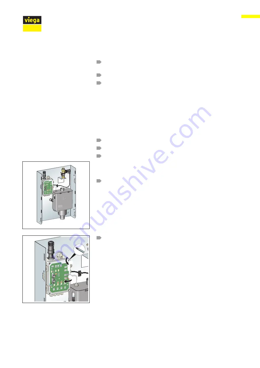
Remove the magnet valve (SW 30).

Use a Phillips-tip screwdriver to remove the lid from the control.

Checking the flow switch

Replacing the floating switch

4x

45°

1.

2.

Handling

Flush valve universal

58 from  62

Содержание 2243.10

Страница 1: ...for automated water exchange in DN 12 80 pipelines Model Year built 2243 10 from 03 2016 en_INT Flush valve universal Instructions for Use...

Страница 2: ...Flush valve universal 2 from 62...

Страница 3: ...llation variations 18 2 5 Accessories and spare parts 23 3 Handling 25 3 1 Transport and storage 25 3 2 Assembly information 25 3 2 1 Mounting conditions 25 3 2 2 Potential equalisation 26 3 2 3 Insta...

Страница 4: ...46 3 5 2 Troubleshooting 53 3 6 Care and maintenance 55 3 6 1 General notes 55 3 6 2 Carrying out inspections 56 3 6 3 Perform maintenance 56 3 6 4 Repairing 58 3 6 5 Care 62 3 7 Disposal 62 Table of...

Страница 5: ...rvice this product This restriction does not extend to possible operating instructions The installation of Viega products must take place in accordance with the general rules of engineering and the Vi...

Страница 6: ...rope Germany These should serve as recommendations in the absence of corresponding national regulations The pertinent national laws stand ards regulations and guidelines as well as other technical gui...

Страница 7: ...ater level The control does not perform a water exchange independ ently or automatically Water exchange must be triggered by enabling the binary input referred to a potential or the analog voltage inp...

Страница 8: ...ructions for use 1 5 2 4 3 6 Fig 1 Overview of flush valve 1 Flow switch 2 Magnet valve 3 floating switch 4 siphon with integrated overflow monitoring floating switch 5 base support 6 control Product...

Страница 9: ...g outputs 2 Bush flush command voltage and event signaling output 4 20 mA 3 flow switch bush 4 backflow sensor bush 5 magnet valves bushes 6 reset button backflow 7 test button test flushing 8 connect...

Страница 10: ...1 2 4 3 Fig 3 Magnet valve overview 1 fixing flange 2 magnetic coils 3 flow control 4 valve body Magnet valve Product information Flush valve universal 10 from 62...

Страница 11: ...1 4 3 2 Fig 4 Flush switch overview 1 Flow switch 2 union nut 3 T piece 4 union nut Flow switch Product information Flush valve universal 11 from 62...

Страница 12: ...for connection to DN 12 80 manifold or riser pipes One flush valve each regulates the water exchange in the cold water and hot water pipes The flush valve can be placed in the following spots n at th...

Страница 13: ...t to DIN 1988 600 can be set at the control unit in increments of approx 12 l min setting range 12 l min to 45 l min see Flowthrough volumes at flow pressure 0 3 MPa 3 bar on page 45 The flowthrough v...

Страница 14: ...flow switch also signals improper flowthrough without flushing command e g in case of a defective magnet valve etc The following functions can be set by means of floating contacts see Fig 6 n Message...

Страница 15: ...utputs are digital outputs potencial free N O contacts The connectors 4 6 and 7 are binary outputs which can be evaluated in an isolated circuit Connector 5 is a binary input which can be actuated in...

Страница 16: ...sage Contact closed Contact open 4 Fault or oper ating Normal opera tion Control current less magnet valve short circuited or defective 6 Water exchange ongoing or leaks Flowthrough 6 l min No flowth...

Страница 17: ...Mains frequency 50 60 Hz Supply voltage internal 24 V DC SELV Supply current Max 1 25 A Standby 0 75 W Power consumption power pack 30 W Operating temperature 5 50 C Backflow sensor Protection class...

Страница 18: ...bar 10 19 25 30 0 2 MPa 2 bar 12 22 32 40 0 3 0 8 MPa 3 8 bar 12 24 35 45 2 4 Information for use 2 4 1 Installation variations Fig 7 Viega Steptec installation diagram For mounting see Viega Steptec...

Страница 19: ...Fig 8 Viegaswift installation diagram For mounting see Viegaswift Viega Eco Plus on page 31 Product information Flush valve universal 19 from 62...

Страница 20: ...Fig 9 Viega Eco Plus installation diagram For mounting see Viegaswift Viega Eco Plus on page 31 Product information Flush valve universal 20 from 62...

Страница 21: ...Fig 10 Installation diagram concealed mounting For mounting see Concealing mounting on page 32 Concealing mounting Product information Flush valve universal 21 from 62...

Страница 22: ...Fig 11 Installation diagram wall mounting For mounting see Wall mounting on page 32 Wall mounting Product information Flush valve universal 22 from 62...

Страница 23: ...Article Cover set wall mounting 2243 11 735 197 Cover set for concealed mounting 2243 12 735 203 Maintenance set 2243 14 735 227 Shut off for wall mounting ball valve DN 25 2270 1 587 048 Shut off for...

Страница 24: ...DN 20 2137 09 624 217 Viega Steptec fasteners 8437 90 min 4 pc 494 179 Viega Swift Eco Plus fastener 8013 23 min 4 pc 6 pc recommended 308 278 Product Model Article Control unit 2243 15 735 234 Flow...

Страница 25: ...e sealants approved by the DVGW pursuant to DIN 30660 and DIN EN 751 2 The flush valve must either be connected to a higher level control such as building control system BCS which cen trally monitors...

Страница 26: ...a live part can lead to the whole piping system and components connected to it e g radia tors becoming energised Only allow electrical work to be carried out by qualified electricians Integrate the b...

Страница 27: ...3 2 3 Installation dimensions 120 600 123 5 62 1 592 3 515 495 3 418 8 40 10 125 125 430 138 Fig 13 Flush valve dimensions Handling Flush valve universal 27 from 62...

Страница 28: ...423 491 12 16 21 97 70 598 0 5 666 123 529 Fig 14 Dimensions concealed mounting cover Handling Flush valve universal 28 from 62...

Страница 29: ...wall mounting cover 3 3 Mounting 3 3 1 Mounting the base The flush valve is delivered pre assembled and ready for connection All components are mounted to the base and have been tested for leak tight...

Страница 30: ...e you a better view the base is shown as empty for the following assembly steps Use Steptec slot nuts model 8437 90 for assembly Push the slot nuts through the cuttings of the base into the open sides...

Страница 31: ...Viega Eco Plus Use hammer head screws model 8013 23 for assembly Push the screws through the cuttings of the base into the rail of the basic element Turn the screws by 90 Place two washers on each sc...

Страница 32: ...holes and insert dowels Put the base on the dowels and hand tighten the screws Align the base once more using a spirit level and tighten the screws The distance between the base and the front edge of...

Страница 33: ...Put the base on the dowels and hand tighten the screws Align the base once more using a spirit level and tighten the screws Further see Chapter 3 3 2 Connecting the flush valve to the pipe line on pa...

Страница 34: ...consumer For maintenance purposes use the following shut off elements n Wall mounted assembly Easytop ball valve model 2270 1 DN 25 EAN 587048 and screw fitting model 2263 EAN 320256 n Concealed mount...

Страница 35: ...t press the Reset button NOTICE In case of an external backflow wastewater leakage over the free discharge area cannot be avoided Take appro priate measures 3 3 3 Connecting electrical components The...

Страница 36: ...uts 2 Bush flush command voltage and signalling output 4 20 mA 3 flow switch bush 4 backflow sensor bush 5 magnet valves bushes 9 reset button backflow 10 test button test flushing 11 connection for 2...

Страница 37: ...nes according to VDE 0100 part 701 Requirements n A 230 V mains connection is available on site n According to VDE 0100 part 701 installation in the protected zones 0 and 1 of shower rooms and bathroo...

Страница 38: ...lamp Return the connector to the power pack You have connected the mains plug See Fig 6 Connecting the external sensor to position 8 For connecting the sensor outputs and inputs use lines with an exte...

Страница 39: ...erform a leakage test with compressed air or inert gases Open the maintenance shut off Flush the water pipe section For information on proper flushing in drinking water installations see the ZVSHK Dat...

Страница 40: ...correctly without back flow and with indication that flowthrough is present Enable all four valves delivery state Check the proper connection of drinking water and wastewater Press the Test button an...

Страница 41: ...cardboard box by 180 sits tighter this way and place it over the device The protective box ensures that the internal area of the base will not be obstructed and that there will be no problems with th...

Страница 42: ...washers on the screw and screw on the wing nuts Insert the frame between the washer and the base Tighten the wing nuts Insert the lid and close it Wall mounting cover Handling Flush valve universal 4...

Страница 43: ...on a unit that is finished but not yet covered We recommend to use compressed air or inert gas for the leakage test The result must be documented 3 4 2 Configuring the control Valve flushing is the on...

Страница 44: ...the number of valves which open during flushing and by the period of time for which the flush command is applied e g via BCS ON ON ON Fig 20 Control switch position ON Recommended setting Volume flow...

Страница 45: ...60 12 24 35 45 70 14 28 41 53 80 16 32 47 60 1 5 90 18 36 53 68 105 21 42 61 79 2 120 24 48 70 90 135 27 54 79 101 150 30 60 88 113 3 180 36 72 105 135 210 42 84 123 158 4 240 48 96 140 180 5 300 60 1...

Страница 46: ...D Indications Faults can be visible in the form of n Leaking water n Reactions from connected external sensors n Evaluation of the signal outputs in the BCS n LED indications at the control Normal ope...

Страница 47: ...All LEDs emit green light All functions are operating properly Handling Flush valve universal 47 from 62...

Страница 48: ...Two red LEDs backflow Handling Flush valve universal 48 from 62...

Страница 49: ...Red light now only from top right LED backflow remedied but Reset has not been pressed executed yet Handling Flush valve universal 49 from 62...

Страница 50: ...All LEDs emit green light Flush command has been applied water is flowing Handling Flush valve universal 50 from 62...

Страница 51: ...Green light now only from one LED each top right centre No flush command water is flowing Handling Flush valve universal 51 from 62...

Страница 52: ...Green light only from one bottom LED red light from 3 LEDs only one valve flush section enabled water is flowing Handling Flush valve universal 52 from 62...

Страница 53: ...y to control Check or establish power supply Magnet valve defective Check magnet valve replace if applicable Short circuit at magnet valve Check magnet valve replace if applicable Check the connection...

Страница 54: ...l flushing command floating or voltage not properly connected Check the connection and the ter minal jumper the terminal at the control Test button for actuation defective Check and if applicable repl...

Страница 55: ...val every 3 days for 10 s no malfunction Consider the safety function of the control in the evaluation done by an external control Leaking water Backflow with water leaks Remedy the backflow 3 6 Care...

Страница 56: ...for all three valves see Chapter 3 4 2 Configuring the control on page 43 n Switch the flushing process for the individual valves on and off subsequently check whether you can hear the flow sounds of...

Страница 57: ...oils After prolonged water exchange the magnet coils get hot Do not touch them Remove the magnet valve SW 30 Unscrew the flow control Replace the flow control seal and nut Screw down the nut of the fl...

Страница 58: ...eed as described in the following Shut the water off De energise the flush valve Disconnect the mains plug from the control CAUTION Risk of burning due to hot magnetic coils After pro longed water exc...

Страница 59: ...he top of the siphon lid on both sides with your hands The front lock comes off With your thumb and forefinger lift the siphon lid by 10 30 mm Slightly pull the lifted siphon lid forward The siphon li...

Страница 60: ...Disconnect the mains plug from the control Open the lid of the control Snap a photo or make a drawing of the existing connections or note their arrangement for proper re installation later on INFO Tho...

Страница 61: ...t and pull off the connection line of the floating switch Use a 10 mm fork spanner to unscrew the four nuts Replace the siphon Re assemble the components in reverse order Shut the water off De energis...

Страница 62: ...cloth Never use chemicals to clean the device 3 7 Disposal Separate the product and packaging materials e g paper metal plastic or non ferrous metals and dispose of in accordance with valid national...

Отзывы: