background image

1800W MITER SAW                                     ENG

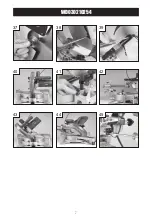
(See Fig 7).
Use the clamp assembly lock at the back of the fence to secure the clamp assembly in position (See 
Fig 8).

10. Spindle lock button

The spindle lock button prevents the blade in the saw from rotating (See Fig 9). Depress and hold the 
spindle lock button while installing, changing, or removing the blade.

11. Rotating lower blade guard

The rotating lower blade guard provides protection from both sides of the blade (See Fig 10). It retracts
over the upper blade guard as the saw is lowered into the workpiece.

12. Dust bag

The dust bag fits over the dust extraction port. For more efficient operation, empty the dust bag when it
is no more than half full. This allows better air flow through the bag (See Fig 11).

13. Attaching the side bars

The side support bars help to support the material when working with long workpieces. There are two
location holes for a support bar on either side of the table. Loosen the lock screws with the hex key. 
Ensure the side bars are fully inserted before using them to support the workpiece (See Fig 12).
The side support bar locking screws must be tightened to secure the support bars in position (See Fig
13).

14. Trench depth adjustment

In its normal position, the trenching stop permits the saw blade to cut right through a workpiece. When
the saw arm is lifted, the trenching stop can be moved to the left so that the trenching depth adjustment 
screw contacts the stop as the saw arm is lowered (See Fig 14).
This restricts the cut to a “trench” in the workpiece. The depth of the trench can be adjusted with the 
trenching depth adjustment screw (See Fig 15) and locked in position with the trenching depth lock nut 
(See Fig 16).

15. Turning on and off

1) Pull in switch trigger to start the unit (See Fig 17).
2) To turn the saw off release the on/off trigger switch.

16. Turning on the laser line generator

The laser line generator emits a single beam of pure red light to guide you as you cut. It improves 
operator cutting vision, enables faster set-up, increases accuracy and improves safety. To turn on the
laser lines press the laser light on/off switch (See Fig 18). To turn off the laser press the laser light 
on/off switch one more time.

17. Setting the table square with the blade

1) Make sure that the electrical plug is removed from the power point.
2) Push the saw arm down to its lowest position and engage the release knob to hold the saw arm in 
the transport position.

15

Содержание WD030210254

Страница 1: ...Miter saw WD030210254 1800W...

Страница 2: ...confident that you will appreciate the quality of the product and you will be entirely satisfied with your purchase Please read carefully the user safety and operating instruction on how to operate th...

Страница 3: ...WD030210254 3 20 16 6 4 2 1 3 10 7 9 5 8 11 14 12 27 28 26 25 24 18 17 15 19 21 22 23 29 34 35 36 30 32 31 33 13...

Страница 4: ...WD030210254 4 1 1 2 2 4 4 5 5 7 7 8 8 10 10 11 11 3 3 6 6 9 9 12 12 3 2 1 6 5 4 9 8 7 12 11 10...

Страница 5: ...WD030210254 5 13 1 14 2 16 4 17 5 19 7 20 8 22 10 23 11 15 3 18 6 90 24 12 15 14 13 18 17 16 21 20 19 24 23 22...

Страница 6: ...WD030210254 6 25 13 26 14 28 16 29 17 31 19 32 20 34 22 35 23 90 27 15 30 18 33 21 36 24 27 26 25 30 29 28 33 32 31 36 35 34...

Страница 7: ...WD030210254 7 37 13 38 14 41 17 43 19 44 20 40 16 16 39 15 42 18 45 21 39 38 37 42 41 40 45 44 43...

Страница 8: ...bar locking screws Clamp assembly lock x2 Clamp assembly Laser cover Slide bars Saw arm Slide lock Dust extraction port Guard retraction arm Upper fixed blade guard Hex key Carrying handle Guard relea...

Страница 9: ...contact with earthed or grounded surfaces such as pipes radiators ranges and refrigerators There is an increased risk of electric shock if your body is earthed or grounded c Do not expose power tools...

Страница 10: ...er tool or these instructions to operate the power tool Power tools are dangerous in the hands of untrained users e Maintain power tools Check for misalignment or binding of moving parts breakage of p...

Страница 11: ...ged saw blades Unsharpened or improperly set saw blades produce narrow kerf causing excessive friction blade binding and kickback 16 Always use saw blades with correct size and shape of arbor holes Sa...

Страница 12: ...the same as the voltage given on the rating plate The power tool is fitted with a two core cable and plug Remove the main plug from socket before carrying out any adjustment or servicing SYMBOLS To re...

Страница 13: ...fault has been rectified Failure to do so could result in serious personal injury 1 Remove all loose parts from the carton 2 Remove the packing materials from around the saw 3 Using the carrying handl...

Страница 14: ...down 6 Slide lock When tightened the slide lock prevents the saw head from sliding Tighten the slide lock during transportation See Fig 4 7 Mitre table lock The mitre table lock is used to lock the t...

Страница 15: ...to secure the support bars in position See Fig 13 14 Trench depth adjustment In its normal position the trenching stop permits the saw blade to cut right through a workpiece When the saw arm is lifte...

Страница 16: ...5 bevel angle See Fig 25 26 18 Setting the fence square with the table 1 Make sure that the electrical plug is removed from the power point 2 Push the saw arm down to its lowest position and engage th...

Страница 17: ...guard 12 Replace the outer blade washer See Fig 37 13 Depress the spindle lock button and replace the flat washer and blade bolt 14 Use the hex key to tighten the blade bolt securely tighten in an an...

Страница 18: ...e to stop rotating before raising the blade out of the workpiece Wait until the blade stops before removing the workpiece 22 Bevel cut A bevel cut is made by cutting across the grain of the workpiece...

Страница 19: ...en 0 and 45 Tighten the bevel lock 6 Place the workpiece flat on the table with one edge securely against the fence If the board is warped place the convex side against the fence If the concave side i...

Страница 20: ...aser line to align the blade with the pencil mark on the workpiece 5 After each use clean the laser light assembly as described below Switch off the laser light switch and then remove the plug from th...

Страница 21: ...work properly check the saw blade for sharpness replace new one if worn 3 If a fault can t be rectified return the power tool to an authorized dealer for repair ENVIRONMENT PROTECTION Waste electrica...

Страница 22: ...1800W MITER SAW ENG EXPLOSIVE VIEW 22...

Страница 23: ...bearing press plate 2 19 Anti finger touch plate 1 59 Gear case cover 1 20 Lock washer 2 60 Screw 2 21 Sunk screw 2 61 Blade flange inner 1 22 Circlip 1 62 Blade 1 23 Gear lock pin spring 1 63 Blade f...

Страница 24: ...Mitre pointer 1 99 Lock pin 1 141 Screw 1 100 Rolled pin 1 142 Rolled pin 1 101 Lock pin spring 1 143 Lock boot 1 102 Lock pin cap 1 144 Lock bolt 1 103 Big torsion spring 1 145 Lock handle 1 104 Spri...

Страница 25: ...5 Knob 2 173 Big washer 2 166 Support arm 1 174 Shield lock sheet 1 167 Support pole 1 175 Washer 2 168 Socket head screw 4 176 Spring washer 2 169 Washer 4 177 Screw 2 170 Fence 1 178 Spring 1 171 Du...

Страница 26: ...26 WD030210254...

Страница 27: ...27 WD030210254...

Страница 28: ...MADE IN CHINA Copyright WIDO Machinery Co Ltd All rights reserved www widopt com...

Отзывы: