


Operator’s Manual Victory FMHDH Series - Page 36 of 52 -
Version 2.0
3.
Block the implement to prevent it from going downward.
4.
Slide the PTO shaft's inner yoke (implement end) onto the input shaft.
Secure the PTO shaft with the yoke locking device.
5.
Slide the PTO shaft's outer yoke (tractor end) over the tractor output shaft.
Secure the PTO shaft with the yoke locking device.
6.
Move the PTO shaft back and forth to ensure that both ends are secured (to the tractor and
the implement).
7.
Your PTO shaft comes with a chain on the shield. Secure the chain to the tractor and the
implement. This will prevent the protection from spinning during operation.
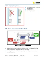
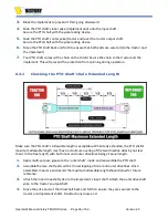
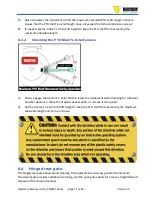
6.3.1
Checking the PTO Shaft
’s
Safe Extended Length
Make sure the PTO s
haft’s collapsible length is acceptable.
When fully extended, the PTO shaft's
maximum allowable length must have a minimum overlap of the two driveline sides by not less
than 1/3 the free length, with both inner and outer drivelines being of equal length.
1.
Apply multi-purpose grease to the
‘
outer shaft
’
inside and reassemble the PTO shaft.
2.
Assemble the two shaft parts with 1/3 overlapping of inner and outer drivelines. Once
assembled, measure and record the maximum allowable length shown below for future
reference.
3.
Attach the inner driveshaft
yoke to the implement’s input shaft. Attach the outer
driveshaft
yoke to the
tractor’s output shaft.
4.
Move the yoke ends of the driveshaft back and forth to ensure they are secured to the
tractor and implement shafts. Re-attach any loose end.


