3.
Alternate turning the depth feed nut with
turning the manual drive nut . Do NOT turn the
depth feed nut more than 0 .0039 inches/0 .1
mm (one line) per rotation .
NOTICE
• Do NOT turn the depth feed nut more
than 0.0039 inches/0.1 mm (one line)
at once.
Failure to follow this instruction could
overload the tool, resulting in reduced tool
life or tool damage.
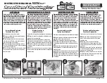
4.
To check the groove diameter during
grooving, use the groove confirmation gauge set
provided . Place the tab of the gauge lengthwise
into the groove . If there is space between the
long edge of the gauge and the pipe length
when the tab meets the bottom of the groove,
continue grooving . If there is no space, stop
grooving and measure with the provided
Go/No-Go Groove Diameter Tape .
If desired, groove diameter adjustment nuts
may be set at this point for repeatability
while grooving pipe of the same diameter
and schedule . With the rolls fully engaged in
the groove, tighten the first groove diameter
adjustment nut against the tool head . Tighten
the second groove diameter adjustment nut
against the first to lock the setting in place .
NOTICE
• The groove confirmation gauge is
provided for convenience during the
grooving process. The final groove must
still be checked with the provided groove
diameter tape to ensure that it meets
Victaulic specifications.
5.
While supporting the tool, loosen the depth
feed nut and remove the tool from the pipe .
6.
Carefully check the groove diameter of
the pipe (“C” dimension) with the provided
Go/No-Go Groove Diameter Tape .
14
REV_A
TM-RG1210
/ Operating and Maintenance Instructions Manual
Содержание RG1210
Страница 2: ......
Страница 22: ...This page intentionally blank ...