background image

Chapter 1

Getting started

Attaching components

ONA-800 Getting Started Guide

April 2022

22142812, R011

Page 7

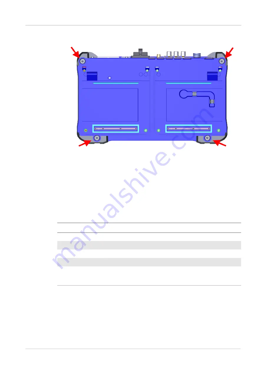
Figure 7

Fastener locations

Attaching modules

This section describes how to attach modules to the ONA-800.

Solution and Fiber Module Carrier modules

Table 5

 lists the Solution modules you can attach to the ONA-800 base.

The following procedure describes how to attach a Solution or Fiber Module Carrier 

module to the ONA-800.

To attach a Fiber Module carrier or Solution module

1

Power down the ONA-800 and disconnect from AC power.

Table 5

Solution Modules

Module

Description

SPA06MA

Spectrum Analyzer with 6 GHz RF and 25 Gbps Optical hardware. 

SPA06MA-O

Spectrum  Analyzer with 6 GHz RF.

RA44MA-O

Radio Analysis Module (44 GHz)

RA18MA-O

Radio Analysis Module (18 GHz)

E81FMC1

Fiber Module Carrier module that allows you to install Fiber 

Modules. See 

Table 7 on page 10

 for a list of supported Fiber 

Modules.

Содержание OneAdvisor ONA-800

Страница 1: ...ONA 800 Getting Started Guide R011 ...

Страница 2: ......

Страница 3: ...nc and any use of such marks by Viavi is under license All other trademarks and registered trademarks are the property of their respective owners Copyright release Reproduction and distribution of this guide is authorized for US Government purposes only Terms and conditions Specifications terms and conditions are subject to change without notice The provi sion of hardware services and or software ...

Страница 4: ...ONA 800 Getting Started Guide Page iv 22142812 R011 April 2022 ...

Страница 5: ...afety and compliance information on page vi California Proposition 65 on page vi Federal Communications Commission FCC on page vi EU WEEE and Battery Directives on page vii EU REACH on page vii EU CE Marking Directives LV EMC RoHS on page viii Korea Certification on page viii Pollution Degree 2 Category under IEC 61010 1 on page ix ...

Страница 6: ...ay not cause harmful interference and 2 this device must accept any interference received including interference that may cause undesired operation The equipment was tested and found to comply with the limits for a Class A digital device pursuant to Part 15 of the FCC Rules These limits are designed to provide reasonable protection against harmful interference when the equipment is operated in a c...

Страница 7: ... est conforme aux d Innovation Sciences et Développement économique Canada applicables aux appareils radio exempts de licence L exploitation est autorisée aux deux conditions suivantes 1 l appareil ne doit pas produire de brouillage 2 l utilisateur de l appareil doit accepter tout brouillage radioélectrique subi même si le brouillage est susceptible d en compromettre le fonctionnement Device opera...

Страница 8: ...cies Standards web page EU CE Marking Directives LV EMC RoHS The equipment conforms with all applicable CE marking directives Please request an EU Declaration of Conformity for further details EU Radio Equipment Directive In accordance with Article 10 8 of the EU Radio Equipment Directive 2014 53 EU the following table provides information on the frequency bands and the maximum RF transmit power o...

Страница 9: ...Measurement Control and Laboratory Use Part I General Requirements IEC 60825 1 2014 EN 60825 1 2014 Safety of laser products Part 1 Equipment classification and requirements Installation Category Over voltage Category II under IEC 60664 1 Pollution Degree 2 Category under IEC 61010 1 Laser Safety The provisions contained in two standards define the safety procedures to be observed both by users an...

Страница 10: ...senting different safety thresholds Laser classes Standards IEC 60825 1 2014 and FDA 21 CFR 1040 10 VFL option Class 2 OTDR modules Class 1 Class 1M All plug in fiber optic transceiver modules Class 1 Warning labels for the laser classes Due to the reduced dimensions of the optical modules it is not possible to attach the required warning labels to them In line with the provisions of Article 7 1 o...

Страница 11: ...011 Page xi The user must take the necessary precautions concerning the optical output of the instrument and follow the manufacturer s instructions Additional safety information Safety information is provided in the document Safety Instructions ONA 800 Base Unit 22137678 which is shipped with the ONA 800 ...

Страница 12: ...Regulatory compliance Additional safety information ONA 800 Getting Started Guide Page xii 22142812 R011 April 2022 ...

Страница 13: ... EU Radio Equipment Directive viii Korea Certification viii Japan Radio Law viii Safety standards compliance viii Safety and compliance information ix Laser Safety ix Laser classes ix Warning labels for the laser classes x About this Guide xiv Purpose and scope xv Assumptions xv Conventions xv Technical assistance xvii Chapter 1 Getting started 1 About the ONA 800 2 Unpacking and inspection 2 What...

Страница 14: ...re options 23 Updating the system software 23 Updating the system software using a USB drive 23 Downloading the software and extracting to a USB drive 23 Performing a software update using a USB drive 24 Updating the system software over the network 25 Job Manager 26 Test plans 26 Creating test plans 26 Running jobs 27 Freeform jobs 28 Synchronizing to the StrataSync server 29 Chapter 3 Powermeter...

Страница 15: ...tablishing a connection 44 Wired Ethernet Connection 45 WiFi Connection 45 Smartphone with Data Tethering 46 Launching the utility 46 Launching the utility on the instrument 47 Testing your connection 47 Launching the utility on your PC or mobile device 47 Displaying the instrument s user interface 48 Transferring files 48 Displaying and modifying connection settings 49 Appendix A Physical Specifi...

Страница 16: ...Guide April 2022 22142812 R011 Page xiv About this Guide This section explains how to use this Getting Started Guide Purpose and scope on page xv Assumptions on page xv Conventions on page xv Technical assistance on page xvii ...

Страница 17: ...r switches that you press or flip on a physical device Press the On button Press the Enter key Flip the Power switch to the on position Buttons links menus menu options tabs or fields on a PC based or Web based user inter face that you click select or type information into Press the On button Click File Properties Click the Properties tab Type the name of the probe in the Probe Name field Director...

Страница 18: ...AUTION or ALERT message See Table 3 for more information This symbol located on the equipment battery or the packaging indicates that the equipment or battery must not be disposed of in a land fill site or as municipal waste and should be disposed of according to your national regulations Table 3 Safety definitions Term Definition DANGER Indicates a potentially hazardous situation that if not avoi...

Страница 19: ...r must take the necessary precautions concerning the optical output of the instrument and follow the manufacturer s instructions Technical assistance For technical assistance call 1 844 GO VIAVI For the latest TAC information go to http www viavisolutions com en services and support support technical assistance ...

Страница 20: ...xplains how to use this Getting Started Guide The topics discussed in this chapter are as follows About the ONA 800 on page 2 Unpacking and inspection on page 2 ONA 800 base on page 3 Additional Modules on page 5 Attaching the screen on page 6 Attaching modules on page 7 Powering the base unit on page 12 ...

Страница 21: ...o variants Table 4 describes the ONA 800 base variants Unpacking and inspection VIAVI typically ships our instruments using anti static packing material to stabilize the components inside the box When unpacking the components verify that all the items you ordered are included in the package Accessories may be shipped in a separate box After you unpack the components examine the top bottom front an...

Страница 22: ...terials in case you need to repackage the components for shipment What s included with the base unit The ONA 800 base unit ships with the following equipment One field replaceable Lithium Ion battery C5BATTERY98 AC adapter G700050127 and cord Up to two dummy modules depending on the number of solution modules ordered LCD screen protector Soft shell travel case ONA 800 base Figure 2 shows the top p...

Страница 23: ... April 2022 Figure 3 shows the right and left side panels Figure 3 Right and left side panels Figure 4 shows the back panel without CAA OTDR or dummy modules attached Figure 4 Back panel no modules 1 Modules 2 Cooling fans 3 Battery access door 1 Screws 2 ESD ground 3 Module connector ports ...

Страница 24: ...bilities and operation of your specific Solution or Fiber Module Carrier modules PEM The ONA 800A MF2 supports the addition of the ONA MF2 PEM Power Extension Module PEM allowing you to add additional batteries to the ONA 800 for an extended battery runtime You can attach up to two PEMs providing the ONA 800 with 3 batteries 2 external 1 internal for a total of 244Wh Figure 5 shows the PEM Figure ...

Страница 25: ...ns describe how to install components to the ONA 800 base Attaching the screen The following procedure describes how to attach the screen to the ONA 800 base unit To attach the screen to the base unit 1 Set the screen onto the base ensuring the mating connectors between the two pieces are aligned as shown in Figure 6 Figure 6 Set screen to base 2 Set unit so you have access to the back Using the H...

Страница 26: ...escribes how to attach a Solution or Fiber Module Carrier module to the ONA 800 To attach a Fiber Module carrier or Solution module 1 Power down the ONA 800 and disconnect from AC power Table 5 Solution Modules Module Description SPA06MA Spectrum Analyzer with 6 GHz RF and 25 Gbps Optical hardware SPA06MA O Spectrum Analyzer with 6 GHz RF RA44MA O Radio Analysis Module 44 GHz RA18MA O Radio Analys...

Страница 27: ... Figure 8 Figure 8 Module to screen 4 Insert the hex key in the brass fittings on the rear of the module and tighten the internal captive fasteners to secure the module to the display 5 Place the ONA 800 base onto the module ensuring the mating connectors are aligned as shown in Figure 9 Figure 9 ONA 800 base to module 6 Using the hex key tighten the captive fasteners on the rear of the base that ...

Страница 28: ...d insert them into the base at a 45 to 60 degree angle 4 Pivot the module down towards the connector as shown in Figure 10 Figure 10 Pivot module down 5 Seat the module into the connector with slight pressure 6 Tighten the screws on the module The following procedure describes how to remove CAA OTDR modules To remove expansion modules 1 Power down the ONA 800 and disconnect from AC power Table 6 E...

Страница 29: ...OSA 110R PC Compact with In Band OSNR 2304 8491 140 OSA 110R APC Compact with In Band OSNR EOSA610B APC HIGH RESOLUTION OSA MODULE VERSION B EOSA610B APCFC HIGH RESOLUTION OSA MODULE VERSION B EOSA610B PC HIGH RESOLUTION OSA MODULE VERSION B OTDR modules E8123AV PC High Resolution OTDR Module AV 850 1300nm PC connector SC adapter Std E8146A PC OTDR Module A EF 850 1300nm and 1310 1550nm PC connect...

Страница 30: ...ach a Fiber Module carrier or Solution module on page 7 3 Slide the plug in module into the Fiber Module Carrier module as shown in Figure 11 Figure 11 Insert plug in module 4 Tighten the thumb screws E8129D 62 APC OTDR Module D 1550 Filtered 1625nm APC connector SC adapter Std E8129D 62 PC OTDR Module D 1550 Filtered 1625nm PC connector SC adapter Std E8136D APC OTDR Module D 1310 1550 1625nm APC...

Страница 31: ...adapter Battery Installation The base unit can operate supplied by the AC power adapter shipped with the unit or by battery Figure 12 shows the battery label Figure 12 ONA 800 battery label CAUTION Do not attempt to run the ONA 800 in an enclosure such as the soft shell travel case Doing so may damage the unit CAUTION The Lithium Ion batteries shipped with the unit can explode if incorrectly insta...

Страница 32: ...atings of the power adapter are 100 240V AC 50 60Hz and it auto ranges between 90 264V AC and 47 63Hz The mains supply cord used with the power adapter must be grounded with a connection to protective earth 1 Battery access door 2 Field replaceable Lithium Ion battery NOTE Before connecting an AC power adapter to the base unit refer to the label on the adapter Figure 13 to confirm that it is the c...

Страница 33: ...Chapter 1 Getting started Powering the base unit ONA 800 Getting Started Guide Page 14 22142812 R011 April 2022 Figure 13 ONA 800 AC power adapter label ...

Страница 34: ...on page 16 Setting up remote access on page 21 Setting up remote access on page 21 Connecting to a Wi Fi network on page 21 Setting up a Bluetooth connection on page 21 Using Smart Access Anywhere on page 22 Enabling software options on page 22 Updating the system software on page 23 Job Manager on page 26 Synchronizing to the StrataSync server on page 29 ...

Страница 35: ...Home Screen The Home screen provides access to the Tests Job Manager and System pages You can return to the Home screen at any time by clicking the Home button in the top left corner of the screen Figure 15 shows the Home button Figure 15 Home button Favorites The Favorites page provides access to test pages identified as Favorites and the most recently visited test pages Figure 16 shows the Favor...

Страница 36: ...orites from the Favorites page 1 Open the Favorite page by pressing Home then pressing Favorites 2 Press the Edit favorites list button The items in Favorites are outlined in purple signifying they are now able to be edited 3 Click and drag the test from Recent to Favorites To add an item to Favorites from a test page 1 On the test page you want to add select the Save button from the side menu as ...

Страница 37: ...they are now able to be edited 3 Click the item you want to edit to select it then click it again to enter it into Edit mode 4 Edit the item a To change the name click the item s name and enter a new one using the on screen keyboard b To change the icon i Click the icon The Load Icon window appears ii Select the new icon then press the Load Icon button The item s icon has been changed To remove an...

Страница 38: ...and generate a report Each time you generate a report your instrument will automatically insert the Customer Name Job Number Technician ID and Test Location that you specified in the Job Manager into the report heading See Job Manager on page 26 for more information System The System screen provides access to tools for viewing system information and performing other tasks as required NOTE Addition...

Страница 39: ... time settings Region Specify international settings including the language of the user interface Display Adjust the brightness level of the touchscreen enable the screen saver and when required calibrate the touchscreen display Remote View and manage remote access settings including when required VNC and Smart Access Anywhere settings Upgrade Perform system software updates Test Set Lock Manage l...

Страница 40: ... and then select Network 2 Select Wi Fi and then select the Enable Wireless Adapter check box to display a list of available wireless networks 3 Select a network and then enter the access credentials Setting up a Bluetooth connection 1 Select System on the menu bar and then select Bluetooth 2 Enable the following check boxes Enable Bluetooth Allow other devices to pair with this device Web Browser...

Страница 41: ...the instru ment s file manager utility You can also rename and delete files or create rename and delete directories See Using Smart Access Anywhere on page 13 for more information Enabling software options Software options may be available on the unit or purchased separately For information about purchasing software options contact the VIAVI Solutions Sales Office for your region Viewing available...

Страница 42: ...tware using a USB drive on page 23 Updating the system software over the network on page 25 Updating the system software using a USB drive Download the system software to a PC and then extract it to a USB drive with at least 1 GB available space VIAVI recommends that the USB drive have no other content stored on it The update process when using a USB drive involves the following procedures Downloa...

Страница 43: ...nd then select USB The release number of the software available on the USB drive appears Note the following symbols that may appear beside the release number on the USB stick An equals symbol indicates that the software on the USB stick and the software on installed on the unit are the same that is have the same release number A down arrow symbol indicates that the software on the USB stick is an ...

Страница 44: ...ials 4 Select Connect 5 After the unit accesses the server select the link for the software file for the unit Note the following symbols that may appear beside the release number of the software file An equals symbol indicates that the software on the USB stick and the software on installed on the unit are the same that is have the same release number A down arrow symbol indicates that the softwar...

Страница 45: ...ion and the pass fail status Creating test plans The following procedure describes how to create a test plan using the on line tool To create a test plan 1 Using a browser on a PC or laptop log in to https jobmanager stratasync viavisolutions com 2 In the Job Information section enter the Job Number Customer Location A Technician ID Report Logo File optional 3 In the Test Plan section add tests to...

Страница 46: ...er screen appears listing the jobs loaded onto the device as shown in Figure 20 Figure 20 Job Manager screen 2 Select the Job you want to run by tapping Set as Current The Job moves to the top of the list expanded to show the test plan as shown in Figure 21 Figure 21 Current Job 3 Press the button for each test you want to run When the Job is complete you can create a report The following procedur...

Страница 47: ...een 2 Tap the Create Report button The Create Report screen appears as shown in Figure 23 Figure 23 Create Report screen Freeform jobs You can use the Job Manager to create an empty Freeform job that allows you to run ad hoc tests and record the results in a consolidated report The following procedure describes how to use an empty job To create and use empty jobs 1 Tap Job Manager in the left hand...

Страница 48: ...ld be synchronized with a VIAVI server via the Internet using an optional subscription based service called StrataSync In addition to the latest operating software synchronization also uploads user files saved on the unit to the StrataSync server A connection to the Internet would be provided upon receipt of the unit and on a regular daily basis thereafter to ensure that the most currently issued ...

Страница 49: ... account ID obtained from VIAVI Ensure that an account ID is available before attempting to access the StrataSync server 4 Optionally enter an ID in the Technician ID field A default technician ID is provided This ID can be modified at any time 5 Select Start Sync to initiate a connection to the StrataSync server Synchronization begins when a connection to the server is established NOTE During Syn...

Страница 50: ... VFL This chapter describes the Powermeter and VFL The topics discussed in this chapter are as follows Connection to the power meter and VFL on page 32 Using the power meter on page 32 Storing and reloading results on page 40 VFL function on page 41 Characteristics of the options on page 42 ...

Страница 51: ...gure 25 shows the location of the Optical connectors on the ONA 800 Figure 25 Optical connectors Using the power meter The power meter functions an option chosen at the time of order and incorporated into the ONA 800 platform in the factory To activate the function 1 Press the HOME button 2 Press the Tests button and then select Fiber 1 ONA PMVFL 3 Press the Powermeter button of the Platform Figur...

Страница 52: ...eters In the Setup menu select Measurement Table 10 describes the parameters Table 10 Measurement parameters Parameter Description Wavelength Select wavelength Auto The wavelength of the input signal will be automatically detected and selected to perform the measurement Note The source must also be in Auto mode 850 980 1300 1310 1420 1450 1480 1490 1510 1550 1578 1625 or 1650 nm Measurement perfor...

Страница 53: ...th selected 1 Select the wavelength 2 Select the displayed reference level 3 Enter the new Reference Level value 4 Confirm the value by clicking the check mark button This reference is also automatically available in the Results page using the Standard Ref soft button Attenuator com pensation Choice of level to be applied to the wavelength chosen for the measurement to compensate for the loss due ...

Страница 54: ...e and code the direction must be temporarily changed In the O E direction the information on the origin can be edited and in the E O direction that on the extremity Cable ID Allows the entry of an identification of the cable using the Edition menu Direction The direction shows if the acquisition has been made from the origin to the extremity A B or from the extremity to the origin B A When differe...

Страница 55: ...ecifies the name of the file 1 Select File Filenaming displayed file naming format 2 Using the keypad either Select the pre defined parameters Enter a file name manually Press Auto to apply the name to the file by default Fiber Cable_Id File_ Num _ Lambda _ Direction The name of the file is displayed in gray under the Filenam ing parameter Report As Specifies report types txt file A txt report fil...

Страница 56: ...splayed as shown in Figure 29 Figure 29 Save keypad 2 Enter a name for the configuration file max 20 characters 3 Press the Checkmark button to validate The configuration file is saved with the extension fo_cfg and can be recalled at any time from the File Explorer page Loading an existing configuration You can load a configuration file previously created or available on the platform To load an ex...

Страница 57: ...ess The power measured by the power meter is displayed in large characters in the units selected in the configuration menu along with The mode of transmission of the signal measured The wavelength of the signal measured The reference level expressed in dB The level of Attenuation Compensation Table of results For each fiber being tested the power meter displays a table of nine results corre spondi...

Страница 58: ...e Standard Reference Selects the current result as a reference value to measure the insertion of a link This reference is displayed under the measure ment result until a new reference is performed Keep Result Keeps the result on the corresponding line of the table Clear Table Deletes all the results displayed in the table Clear Table appears as an X Performing a measurement The Powermeter is start...

Страница 59: ... power meter 2 Connect the jumper between the input of the power meter and the output of the source 3 Configure the same wavelength on the source and the power meter The power measured is displayed on the results page of the power meter 4 Press the Standard Ref softkey to save the result displayed as reference value After defining the reference value proceed to the next procedure To perform measur...

Страница 60: ...uitable for short fibers length 5 km or the first few meters of a long fiber To emit a light signal into a fiber 1 Connect the fiber to the VFL port on the connectors panel 2 Press the Tests button and then select Fiber 1 ONA PMVFL 3 Press the VFL button of the Platform to activate the VFL Figure 31 shows the VFL button Figure 31 VFL button The Laser On icon appears in the system tray as shown in ...

Страница 61: ...g Wavelength range 800 to 1650 in steps of 1 nm Calibrated wavelengths 850 1310 1490 1550 1625 1650 nm1 Accuracy at calibrated wavelengths 0 2 dB at 30 dBm Input power range 60 dBm to 10 dBm Maximum resolution 0 01 dB 0 01 nW Measurement range 5 to 50 dBm 45 dBm from 800 to 1250 nm Linearity within the measurement range 0 2 dB VFL option Wavelength 650 nm Maximum power 1 2 mW Length of fiber up to...

Страница 62: ...ity The topics discussed in this chapter are as follows About Smart Access Anywhere on page 44 Licensing on page 44 Downloading and extracting the utility on page 44 Establishing a connection on page 44 Launching the utility on page 46 Displaying the instrument s user interface on page 48 Transferring files on page 48 Displaying and modifying connection settings on page 49 ...

Страница 63: ...tility The Smart Access Anywhere utility must be downloaded and extracted on the work station that you intend to use to connect remotely to the test instrument To download the utility 1 On your workstation open a browser and type the following address http smartaccess updatemyunit net 2 Click on the SmartAccessAnywhere_Vxx xx xx zip link 3 Select Save in the dialog box After the download is comple...

Страница 64: ...need to 1 deter mine the instruments IP address and 2 configure the network proxy if a proxy is used WiFi Connection Figure 34 illustrates a test instrument connected to a workstation using a WiFi connec tion NOTE To connect using WiFi the WiFi option must be installed on the target test instrument To order the option or to determine whether a particular Smartphone has been quali fied by Viavi for...

Страница 65: ... data tethering Figure 36 illustrates a test instrument connected to a workstation using a USB connec tion to a Smartphone that supports data tethering Launching the utility To use the Smart Access Anywhere utility you must 1 establish a connect from your PC or mobile device to the test instrument 2 launch the utility on the test instrument to obtain the required remote access code and then 3 laun...

Страница 66: ...ng your connection Before launching the utility on your workstation you can also optionally test the connec tion between the workstation and target test instrument To test your connection 1 On your workstation launch the Smart Access Anywhere utility 2 Select Test connection The test automatically launches 3 To display connection log details in real time select the See full logs button The connect...

Страница 67: ... for the instrument appears on your workstation s display The VNC icon in the system tray indicates that the remote screen is active Transferring files Single files can be transfered one by one from your PC or mobile device to the instru ment or from the instrument to your PC or mobile device To transfer a file to or from the workstation or instrument 1 On the Introduction page click File Transfer...

Страница 68: ... file manager Displaying and modifying connection settings You can review information about the current remote session at any time To display session information Select the Session icon key Session details appear This page gives information on the connection in real time To modify connection settings 1 Select the Session icon 2 Disconnect the session using the Disconnect button 3 On the session sc...

Страница 69: ...Chapter 4 Smart Access Anywhere Displaying and modifying connection settings ONA 800 Getting Started Guide Page 50 22142812 R011 April 2022 ...

Страница 70: ...tarted Guide April 2022 22142812 R011 Page 51 A Appendix A Physical Specifications This appendix lists the physical specifications of the ONA 800 Topics covered include ONA 800A MF on page 52 Optional modules on page 52 ...

Страница 71: ...rging time depends on the types of tests performed Specified temperatures are internal to battery Type 14 4 V 6 7 A h 92 Wh Lithium Ion Charging Time One battery 100 2 2 hours Charging Temperature 0 to 45oC 32 to 113oF Discharging Temperature 0 to 60oC 50 to 240oF Operating Temperature3 3 Operating Temperature is for base only See the module documentation for more information 0 to 40 C 32 to 104 F...

Страница 72: ... Modules Series User Guide Supporting data sheets are available at www viavisolutions com DTS For Distributed Temperature Sensing DTS module specifications refer to the DTSS and STS Module User Manual Supporting data sheets are available at www viavisolutions com Expansion Modules The following sections describe Expansion modules CAA modules For Cable and Antenna Analyzer CAA modules refer to the ...

Страница 73: ...s com Power Expansion Module PEM Table 15 describes the physical specifications of the PEM Table 15 ONA MF2 PEMphysical specifications Parameter Specification Dimensions Height 130 mm 5 1 in Width 138 mm 5 4 in Depth 41 mm 1 6 in Battery Type 14 4 V 6 7 A h 92 Wh Lithium Ion Charging Time 2 2 hours Charging Temperature 0 to 45oC 32 to 113oF Discharging Temperature 0 to 60oC 32 to 140oF Storage Tem...

Страница 74: ......

Страница 75: ...merica 1 844 GO VIAVI 1 844 468 4284 Latin America 52 55 5543 6644 EMEA 49 7121 862273 APAC 1 512 201 6534 All Other Regions viavisolutions com contacts email TAC viavisolutions com ONA 800 Getting Started Guide 22142812 R011 ...

Отзывы: