31
Step 6
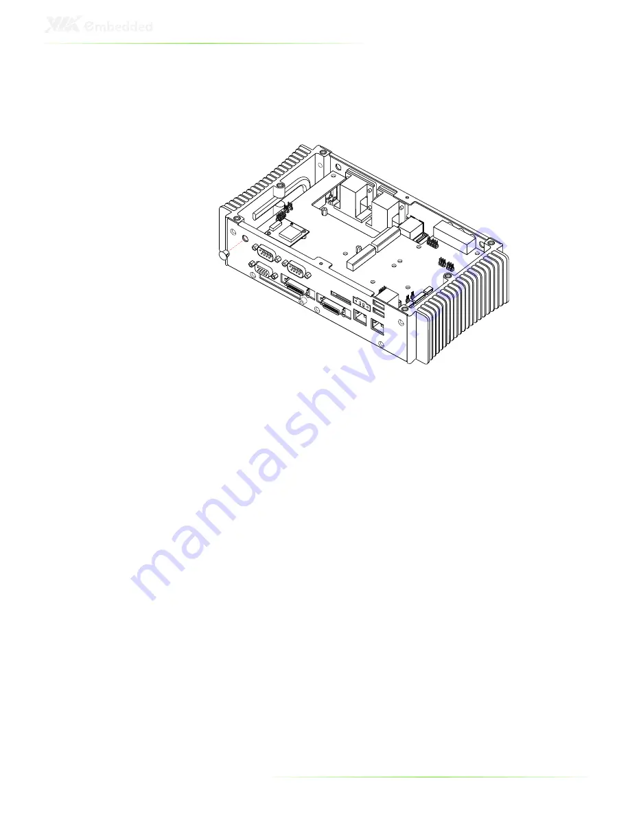
Remove the GPS antenna hole cover from the chassis. To facilitate
removing the cover, use a pair of needle-nose pliers to depress
both locking clips simultaneously.
Step 7
Insert the antenna cable (provided with the GPS kit) into the GPS
antenna hole from the inside. Make sure the flat side of the
antenna jack matches the flat side of the antenna hole.
Step 8
Secure the GPS antenna jack to the chassis with the toothed
washer and nut.
Содержание ART-5450
Страница 12: ...XII ...
Страница 13: ...1 1 Product Overview ...
Страница 21: ...9 ART 5450 DIMENSIONS ...
Страница 22: ...10 ACCESSORIES Power cable 2 pole Phoenix Part 99G33 250073 Mounting Brackets Part 99G42 092136 A1 ...
Страница 48: ...36 HOW TO INSTALL THE MOUNTING BRACKETS Step 1 Prepare the left and right brackets and the four screws ...
Страница 49: ...37 Step 2 Fasten the mounting brackets to the bottom side of the ART 5450 chassis as shown ...
Страница 50: ...38 Step 3 Secure both mounting brackets to the wall table with four screws ...
Страница 52: ...40 Step 4 Connect the power module to the power source using the provided cable ...
Страница 54: ...42 Power Input Connector Pin Signal 1 IGN2 2 GND 3 DC 10 30V 4 ACC 5 GND 6 DC 10 30V 1 3 4 6 ...
Страница 61: ...49 5 BIOS Setup This chapter gives a detailed explanation of the BIOS setup functions ...
Страница 71: ...59 Summary Screen Show Show summary screen Settings Disabled Enabled ...
Страница 85: ...73 USB Storage Function Enable or disable Legacy support of USB Mass Storage Settings Disabled Enabled ...
Страница 86: ...74 FREEDOS CONFIGURATION Boot into FreeDOS The system will boot to FreeDOS Settings Disabled Enabled ...
Страница 100: ......
Страница 101: ...89 6 Driver Installation ...


